-
Welcome to Tacoma World!
You are currently viewing as a guest! To get full-access, you need to register for a FREE account.
As a registered member, you’ll be able to:- Participate in all Tacoma discussion topics
- Communicate privately with other Tacoma owners from around the world
- Post your own photos in our Members Gallery
- Access all special features of the site
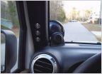 Aux Light Switches
 Just got these in the mail!
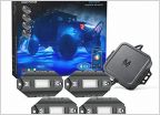 MICTUNING Rock Light Experiences?
 Put a new set of LED strobes on my Taco
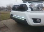 Arsenal Offroad 30" Lightbar
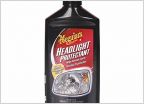 Headlight Restoration Products?
Miserable Hella 500 failure.... again
Discussion in 'Lighting' started by texastacobueno, Mar 23, 2010.