

-
Welcome to Tacoma World!
You are currently viewing as a guest! To get full-access, you need to register for a FREE account.
As a registered member, you’ll be able to:- Participate in all Tacoma discussion topics
- Communicate privately with other Tacoma owners from around the world
- Post your own photos in our Members Gallery
- Access all special features of the site
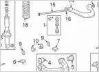 First gen front suspension question...
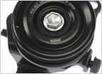 Part number or replacement for adjusting bolt, 2rz-FE
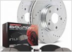 2004 PRERUNNER - BRAKES
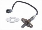 O2 sensor part #'s
 Used shell mounting
1st Gen A/C System Replacement How-To (Seized Compressor)
Discussion in '1st Gen. Tacomas (1995-2004)' started by geodude, Aug 31, 2013.
Page 1 of 9
Page 1 of 9


