

-
Welcome to Tacoma World!
You are currently viewing as a guest! To get full-access, you need to register for a FREE account.
As a registered member, you’ll be able to:- Participate in all Tacoma discussion topics
- Communicate privately with other Tacoma owners from around the world
- Post your own photos in our Members Gallery
- Access all special features of the site
 Blower motor issue
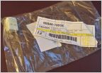
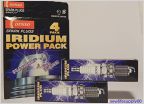 Part # for Denso Spark Plugs (2005 2WD)?
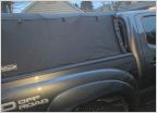 Half-Baked LED bedrail idea - need suggestions
 Paint Chip Repair Experiment
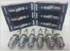 Big drop in gas mileage 2.7L 2TR-FE
 Oil plug leak after I changed oil
OEM Heated Mirrors DIY mod
Discussion in '2nd Gen. Tacomas (2005-2015)' started by Benson X, Dec 18, 2011.
Page 22 of 31
Page 22 of 31
Products Discussed in


