

-
Welcome to Tacoma World!
You are currently viewing as a guest! To get full-access, you need to register for a FREE account.
As a registered member, you’ll be able to:- Participate in all Tacoma discussion topics
- Communicate privately with other Tacoma owners from around the world
- Post your own photos in our Members Gallery
- Access all special features of the site
 DIY Remote Start in 2015 Advice
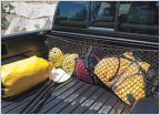 Cargo net question (Amazon)
 Startrooper 13 Tacoma Overlanding Build
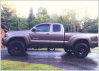 Rubber Mudflaps
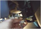 Need remote start install help
 Operation: hit ‘em with the blue lights
12-pin DTRL LED Flasher Modification (2012 Tacoma)
Discussion in '2nd Gen. Tacomas (2005-2015)' started by Sammy1Am, Oct 15, 2012.
Page 1 of 6
Page 1 of 6

