

-
Welcome to Tacoma World!
You are currently viewing as a guest! To get full-access, you need to register for a FREE account.
As a registered member, you’ll be able to:- Participate in all Tacoma discussion topics
- Communicate privately with other Tacoma owners from around the world
- Post your own photos in our Members Gallery
- Access all special features of the site
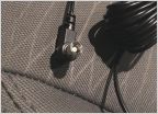 2018 SR Radio Swap (no XM) to Taco 2017 Radio with XM [antenna help please]
 I have a USB Complaint
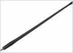 Best Aftermarket Short Antenna
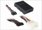 2007 Doublcab Head Unit replacement
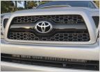 Front camera recs- 2011 honeycomb sport grille
 Midrange/Mid bass speakers for JBL equipped front doors
Big 3 Upgrade
Discussion in 'Audio & Video' started by MJonesTrumpet, Aug 19, 2010.


