-
Welcome to Tacoma World!
You are currently viewing as a guest! To get full-access, you need to register for a FREE account.
As a registered member, you’ll be able to:- Participate in all Tacoma discussion topics
- Communicate privately with other Tacoma owners from around the world
- Post your own photos in our Members Gallery
- Access all special features of the site
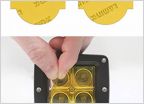 Anyone have experience with Lamin-X film?
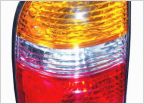 Tail lights
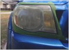 06 original headlights - restoration/ maintenance
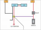 How to make 12V on actually turn lights off
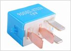 Fog light harness for 4 cylinder?..
 RF interference from LED lights?
Help 3hids 1 works 2 won't
Discussion in 'Lighting' started by DIRT YOTA, Oct 17, 2012.
Page 1 of 3
Page 1 of 3