-
Welcome to Tacoma World!
You are currently viewing as a guest! To get full-access, you need to register for a FREE account.
As a registered member, you’ll be able to:- Participate in all Tacoma discussion topics
- Communicate privately with other Tacoma owners from around the world
- Post your own photos in our Members Gallery
- Access all special features of the site
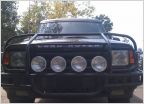 Good placement for PIAA's
 Middle Socket Empty 09 and Up LED Tail Light Bulb Missing
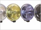 Hella 500ff or hella 500ff black magics?
 DIMMEST bulbs possible for license plate light.
 What LED reverse lights are you using?
 Yellow fog light options
Wiring extra reverse lights to switch and preexisting lights
Discussion in 'Lighting' started by CliffordBRD, Mar 1, 2013.
Page 2 of 4
Page 2 of 4