-
Welcome to Tacoma World!
You are currently viewing as a guest! To get full-access, you need to register for a FREE account.
As a registered member, you’ll be able to:- Participate in all Tacoma discussion topics
- Communicate privately with other Tacoma owners from around the world
- Post your own photos in our Members Gallery
- Access all special features of the site
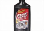 Headlight Restoration Products?
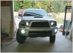 Adding automatic headlights
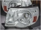 Need New Headlight Housings
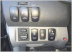 Fog Light Switch
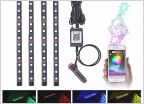 Bluetooth RGB Rock Lights/RGB Led Light Strip Music Sync
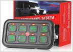 3 way OEM switch for lightbar
Wiring LED lightbar to high beams
Discussion in 'Lighting' started by chipnoreo, Jul 20, 2013.
Page 5 of 5
Page 5 of 5