

-
Welcome to Tacoma World!
You are currently viewing as a guest! To get full-access, you need to register for a FREE account.
As a registered member, you’ll be able to:- Participate in all Tacoma discussion topics
- Communicate privately with other Tacoma owners from around the world
- Post your own photos in our Members Gallery
- Access all special features of the site
 How much are my Hellas worth?
 License plate lighting ideas
 Switchback DRL/front directionals
 Suggestions on upgrading my headlights...2017 Tacoma TRD/OR
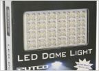 LED Dome lighting
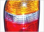 Tail lights
Wiring LED lightbar to high beams
Discussion in 'Lighting' started by chipnoreo, Jul 20, 2013.
Page 1 of 5
Page 1 of 5


