

-
Welcome to Tacoma World!
You are currently viewing as a guest! To get full-access, you need to register for a FREE account.
As a registered member, you’ll be able to:- Participate in all Tacoma discussion topics
- Communicate privately with other Tacoma owners from around the world
- Post your own photos in our Members Gallery
- Access all special features of the site
 Improving The 3rd Generation Tail Lights
 Cheap Switch Panels and Perfecting my Light Game
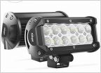 Light Bar Options
 Rear Facing LEDs?
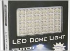 LED Dome lighting
 Hooking up bed lights to door switch
Novice seeking help with Hella 500s how to wire etc...
Discussion in 'Lighting' started by Molon Labe, Jun 15, 2012.


