

-
Welcome to Tacoma World!
You are currently viewing as a guest! To get full-access, you need to register for a FREE account.
As a registered member, you’ll be able to:- Participate in all Tacoma discussion topics
- Communicate privately with other Tacoma owners from around the world
- Post your own photos in our Members Gallery
- Access all special features of the site
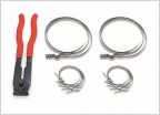 Inner steering bellows clamps
 Is a 09 tacoma rear diff a 8" or a 8.4"?
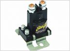 Second battery
 DIY TRUE BOLT ON Cheap Ebay Longbed Flares on a Shortbed!
Electronics Basics and Reference
Discussion in 'Technical Chat' started by larryde09, Jul 23, 2010.
Page 1 of 6
Page 1 of 6

