-
Welcome to Tacoma World!
You are currently viewing as a guest! To get full-access, you need to register for a FREE account.
As a registered member, you’ll be able to:- Participate in all Tacoma discussion topics
- Communicate privately with other Tacoma owners from around the world
- Post your own photos in our Members Gallery
- Access all special features of the site
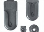 Midland 75 mounting ?????
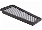 Air filter replacement
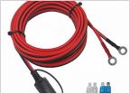 Need help hardwiring power inverter
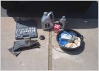 4.0L 1GR 2nd Gen Oil Change Guide
 Before I order 75w90 what is everyone's thoughts on brand?
3RZFE engine rebuild: How To---
Discussion in 'Technical Chat' started by BamaToy1997, May 23, 2013.
Page 1 of 4
Page 1 of 4