

-
Welcome to Tacoma World!
You are currently viewing as a guest! To get full-access, you need to register for a FREE account.
As a registered member, you’ll be able to:- Participate in all Tacoma discussion topics
- Communicate privately with other Tacoma owners from around the world
- Post your own photos in our Members Gallery
- Access all special features of the site
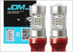 Hyper flash turn signals.
 Bus Bar For Accessories
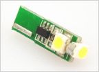 AC control led's
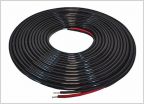 Wire sizing / light bar amp draw question
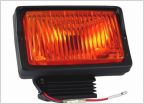 Back to the Future Toyota question??
 Footwell/rear seat dome light controlled LEDS MOD (LOTS OF PICS)
Help with building a wire harness
Discussion in 'Lighting' started by STravis, Jul 9, 2015.
Page 2 of 2
Page 2 of 2


