

-
Welcome to Tacoma World!
You are currently viewing as a guest! To get full-access, you need to register for a FREE account.
As a registered member, you’ll be able to:- Participate in all Tacoma discussion topics
- Communicate privately with other Tacoma owners from around the world
- Post your own photos in our Members Gallery
- Access all special features of the site
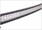 Best 24" LED Bar
 Headlights
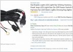 Help an idiot with wiring lights
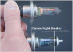 Best Headlight Replacement Bulb?
 Wanting to make the switch to LED headlights
Robbing LEDs from flashlights
Discussion in 'Lighting' started by Bennoclarke, Jan 23, 2016.
Page 2 of 3
Page 2 of 3


