1. Welcome to Tacoma World!

    You are currently viewing as a guest! To get full-access, you need to register for a FREE account.

    As a registered member, you’ll be able to:
    • Participate in all Tacoma discussion topics
    • Communicate privately with other Tacoma owners from around the world
    • Post your own photos in our Members Gallery
    • Access all special features of the site

Fridge Wiring Help (Any Electrical Engineers Out There?)

Discussion in 'Technical Chat' started by weldo, Jul 19, 2016.

  1. Jul 19, 2016 at 5:27 PM
    #1
    weldo

    weldo [OP] Well-Known Member

    Joined:
    Oct 15, 2014
    Member:
    #140423
    Messages:
    1,337
    Gender:
    Male
    First Name:
    Mike
    Pittsburgh, pa
    Vehicle:
    2014 base ac 2.7 5-speed 4x4
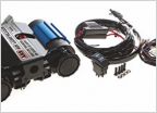
    Hey all, I have a wiring question for anyone well versed in electrical circuits and such. This is regarding a Hemacool refrigerator. Looks like this, a 2 cu ft fridge in a Hardigg case.

    [​IMG]

    So here's the deal, I bought this unit on ebay because I heard they were pretty stout and efficient if a bit big and heavy. The unit has on board 2 small 12V batteries so that it can run independently of a power source for up to 24 hours. This is the main feature I liked because it kept me from having to invest in a dual battery setup.

    The problem is that the wiring harness that connects the batteries to the fridge was missing. The part is called the "Fusible Link Assembly" in the manual. Here's a pic from the manual. I wanna make my own harness.

    _EP38827.jpg

    Here's a pic of the plug on the fridge that this harness plugs into

    _EP38848.jpg

    and some detailed pics of the plug so I can figure out wire placement. I already found the connector I need and ring terminals are no big deal.

    thumbnail_image1.jpg thumbnail_image2.jpg thumbnail_image3.jpg

    I'd expect the positive wires to be red and negative to be black but they all look black in the pics. That makes me think the wire is a fusible wire like this stuff.

    [​IMG]

    So the first question, Would the negative wires have to be fusible or just the positive? Instead of using fusible wire I'd like to put an ATC fuse holder inline and I don't know if the negative wires need one or not. I can guess the capacity because the manual says the unit draws 55W or less on start up. At 12V that's about 4.5A, so I'd guess a 5A fuse would be perfect.

    The next mystery is this little black box. I have no idea what it's for or what it does. Anyone ever see something like it before?

    thumbnail_image4.jpg

    I know these are pretty specific questions, just wondering if anyone has any experience with something like this.

    Thanks for reading guys!
     
    This site contains affiliate links for which the site may be compensated.
    #1
  2. Jul 19, 2016 at 5:42 PM
    #2
    caribe makaira

    caribe makaira Well-Known Member

    Joined:
    Feb 13, 2011
    Member:
    #51121
    Messages:
    11,734
    Gender:
    Male
    Caribbean, Puerto Rico
    Vehicle:
    05 PreRunner TRD Offroad AutoTrans
    Hood Struts, My version Fogs always ON, Map & Overhead Light Mod,
    "(3) Connect the battery power harness to the fusible link assembly (Figure 2-4)."

    Apparently the fusible link wire is on the harness going towards the batteries. No need to assemble the missing part of the harness with said wire.
     
  3. Jul 19, 2016 at 6:03 PM
    #3
    weldo

    weldo [OP] Well-Known Member

    Joined:
    Oct 15, 2014
    Member:
    #140423
    Messages:
    1,337
    Gender:
    Male
    First Name:
    Mike
    Pittsburgh, pa
    Vehicle:
    2014 base ac 2.7 5-speed 4x4
    If I look at this like a simple battery circuit, you wouldn't need any kind of fuse on the negative side, right? In the flow of electrons, the positive is like the supply from the battery and the negative is like the return back to the battery.

    When I wired up my aux fuse box I put the circuit breaker on the positive side not the negative.

    So I think I would only need fuse protection on the positive side.

    Any idea what that little black box is?
     
  4. Jul 19, 2016 at 6:14 PM
    #4
    Arcticelf

    Arcticelf Well-Known Member

    Joined:
    Jul 18, 2015
    Member:
    #159735
    Messages:
    7,653
    Gender:
    Male
    Vehicle:
    Gladiator
    I think that black box is your fusible link. I don't think its 5A though, as thats on smaller control signal wire, not the heavy stuff moving power.

    You'll have to get a volt meter and confirm which pins have power (positive terminal), and which are ground (negative terminal). Your fuze seems to be on a separate wire, so you need to know the rating.
     
    t4daddy likes this.
  5. Jul 19, 2016 at 6:15 PM
    #5
    caribe makaira

    caribe makaira Well-Known Member

    Joined:
    Feb 13, 2011
    Member:
    #51121
    Messages:
    11,734
    Gender:
    Male
    Caribbean, Puerto Rico
    Vehicle:
    05 PreRunner TRD Offroad AutoTrans
    Hood Struts, My version Fogs always ON, Map & Overhead Light Mod,
    I'm guessing it's a diode.

    So you are creating the harness towards the batteries, correct? If so then use the fusible wire.

    Can you trace where the pins to from the connector run to? the top ones coming from the missing black box...I see red & black.
     
  6. Jul 19, 2016 at 6:21 PM
    #6
    t4daddy

    t4daddy Well-Known Member

    Joined:
    Jun 16, 2010
    Member:
    #39041
    Messages:
    7,455
    Gender:
    Male
    North Alabama
    Vehicle:
    2008 PreRunner Double Cab
    This: I'd wager the "little black box" is the fusible link.
     
  7. Jul 19, 2016 at 6:27 PM
    #7
    caribe makaira

    caribe makaira Well-Known Member

    Joined:
    Feb 13, 2011
    Member:
    #51121
    Messages:
    11,734
    Gender:
    Male
    Caribbean, Puerto Rico
    Vehicle:
    05 PreRunner TRD Offroad AutoTrans
    Hood Struts, My version Fogs always ON, Map & Overhead Light Mod,
    The power supply to the "fridge" is not shown, what we see is the connector from the "fridge" towards the batteries. He's making the harness that goes to the batteries. So, the internal controller/supplier is onboard the fridge and If something were to fail the wires in the harness to batteries would behave as fuses, hence fusible link assembly. Fuses go on this panel...

    upload_2016-7-19_21-37-11.jpg
     
    Last edited: Jul 19, 2016
  8. Jul 19, 2016 at 6:57 PM
    #8
    weldo

    weldo [OP] Well-Known Member

    Joined:
    Oct 15, 2014
    Member:
    #140423
    Messages:
    1,337
    Gender:
    Male
    First Name:
    Mike
    Pittsburgh, pa
    Vehicle:
    2014 base ac 2.7 5-speed 4x4
    That is correct. I need to fabricate the harness from the plug in the third picture to the batteries. The plug in the third pic goes to the "motherboard" which is the main control for fridge functions. I do agree that the 2 wires going to the black box are much smaller like signal wires. According to this chart though, even a 22ga AWG wire could carry 5A.

    http://www.engineeringtoolbox.com/wire-gauges-d_419.html

    I'm curious about the diode idea.

    My original plan was to wire up the batteries with the plug just like the pictures using 16ga wire. 16 is the largest gauge the pins used with the connector will accept. Then for the black box thing I was gonna use an ATC fuse holder with a 5A fuse. Then I started second guessing myself.

    The guy who sent me the pictures asked me if I was sure the black box was a fuse. He said there were no markings on it. I assumed since the part was called "fusible link" and i couldn't see any fuses, the black box must be some kind of fuse. But if it was it would certainly be labeled somehow. Then I started thinking, "What if the wires were fusible wires?" Then what the hell is the black box?!

    Thanks for all the ideas guys, it's super helpful!
     
  9. Jul 19, 2016 at 7:11 PM
    #9
    Tom Servo

    Tom Servo Dickweed

    Joined:
    Oct 14, 2014
    Member:
    #140347
    Messages:
    1,243
    Gender:
    Male
    Thornton, CO
    Vehicle:
    2013 DCSB TRD Sport
    ^^^this

    Black box is likely a zener diode used for voltage regulation.
     
  10. Jul 19, 2016 at 7:51 PM
    #10
    caribe makaira

    caribe makaira Well-Known Member

    Joined:
    Feb 13, 2011
    Member:
    #51121
    Messages:
    11,734
    Gender:
    Male
    Caribbean, Puerto Rico
    Vehicle:
    05 PreRunner TRD Offroad AutoTrans
    Hood Struts, My version Fogs always ON, Map & Overhead Light Mod,
    This what I found after reading the operating manual...it's a thermistor. Maybe the unit might function without it, since there's no info on it's specifications.

    upload_2016-7-19_22-51-11.jpg
     
    Sandman614 likes this.
  11. Jul 19, 2016 at 7:51 PM
    #11
    weldo

    weldo [OP] Well-Known Member

    Joined:
    Oct 15, 2014
    Member:
    #140423
    Messages:
    1,337
    Gender:
    Male
    First Name:
    Mike
    Pittsburgh, pa
    Vehicle:
    2014 base ac 2.7 5-speed 4x4
    I think I've had a breakthrough.

    Here's a pic of where the wires go into the motherboard

    _EP38853.jpg

    And here's the wiring diagram zoomed into that plug

    hemacool plug j10.jpg

    Numbers 2, 4, 7 go to "BAT -" and numbers 1, 3, go to "BAT +"

    hemacool j10 term.jpg

    Battery positive wires are red and orange, number 1 and 3 on the plug. Battery negative are black and brown, numbers 2 and 4 on the plug. The small black and red signal wires going to the black box seem to be numbers 6 and 7 on the plug. Number 7 shares a ground and number 6 goes to "THERM_BAT". Perhaps a battery temp sensor.

    A google search found this that looks very similar. It sends battery temp info to whatever controls the charging circuit.

    [​IMG]

    I think I'm getting close here.
     
    Sandman614 likes this.
  12. Jul 19, 2016 at 7:52 PM
    #12
    weldo

    weldo [OP] Well-Known Member

    Joined:
    Oct 15, 2014
    Member:
    #140423
    Messages:
    1,337
    Gender:
    Male
    First Name:
    Mike
    Pittsburgh, pa
    Vehicle:
    2014 base ac 2.7 5-speed 4x4
    Cool, man! I never saw that diagram in the manual I have.
     
  13. Jul 19, 2016 at 7:57 PM
    #13
    caribe makaira

    caribe makaira Well-Known Member

    Joined:
    Feb 13, 2011
    Member:
    #51121
    Messages:
    11,734
    Gender:
    Male
    Caribbean, Puerto Rico
    Vehicle:
    05 PreRunner TRD Offroad AutoTrans
    Hood Struts, My version Fogs always ON, Map & Overhead Light Mod,
  14. Jul 19, 2016 at 8:01 PM
    #14
    weldo

    weldo [OP] Well-Known Member

    Joined:
    Oct 15, 2014
    Member:
    #140423
    Messages:
    1,337
    Gender:
    Male
    First Name:
    Mike
    Pittsburgh, pa
    Vehicle:
    2014 base ac 2.7 5-speed 4x4
    Thanks dude! The one I have doesn't have that block diagram. I wonder if that Blue Sea thing is the same thing? It's a small black thermal sensor with 2 same colored wires. It's the closest I've come so far in searching for things that look like the picture.

    All the help has been great!

    For now I gotta hit the sack. Thanks a again guys, I'll think more on this and check back tomorrow.
     
  15. Jul 20, 2016 at 4:49 AM
    #15
    Arcticelf

    Arcticelf Well-Known Member

    Joined:
    Jul 18, 2015
    Member:
    #159735
    Messages:
    7,653
    Gender:
    Male
    Vehicle:
    Gladiator
    You found schematics, I'd say you're on the right track.
     
  16. Jul 20, 2016 at 8:12 AM
    #16
    tgear.shead

    tgear.shead Well-Known Member

    Joined:
    Aug 20, 2015
    Member:
    #162276
    Messages:
    1,735
    Gender:
    Male
    Uhm, well... I guess we know that you're no electrical engineer.
    The electrons actually flow out of the NEGATIVE side and into the POSITIVE side.
    This is opposite to what you would expect, and is simply a matter of convention.

    You see, when the earliest work was being done with electricity, the people doing this didn't actually know what an electron was, nor obviously did they have any way of actually testing their flow. So they just named the terminals as positive and negative, and it stuck.
     
  17. Jul 20, 2016 at 8:26 AM
    #17
    tgear.shead

    tgear.shead Well-Known Member

    Joined:
    Aug 20, 2015
    Member:
    #162276
    Messages:
    1,735
    Gender:
    Male
    Ok, so here's the thing with the thermistor; they are not all the same. There are literally THOUSANDS of different variations. Differences in the power they can dissipate, differences in the temperature/resistance curves -- and not just by a small margin. You could be looking at a 10 ohm thermistor, or a 10 MILLION ohm, or anything in between. You can also get ones that operate in opposite directions -- ones that resist more as they get hot, or ones that resist more as they get cold. Without knowing the specifications, you can't just throw in some random thing and hope that it works. BUT, you can *probably* leave it out and have the thing work. By leave it out, either have it disconnected, or connected. However, it is also possible that the circuit board is expecting a resistance that is in some RANGE, in which case, you need to replace it with an appropriate resistor.

    Note that taking this thermistor out of the circuit will leave something unprotected, which is potentially dangerous. Batteries can and do explode in the wrong conditions.

    Regarding the fusible links -- note that car voltage is not 12. Normal driving voltage that I see on mine are actually around 13.5, but the voltage in a car can generally vary anywhere between 10 and 15. Either way, leaving only 0.5 amps is not enough. I'd go bigger than that, like 10 amps. BUT, since it appears that this unit runs two wires to two batteries, you should probably be good with a 5 amp fuse on EACH.

    The proper placement for fuses or fusible links is **as close to the battery as technically possible**. One of the reasons why fusible links are so great, is because it can BE the wire running directly from the battery. This is the best protection possible, because there is no length of wire at all that could short out before the fuse block.
     
  18. Jul 20, 2016 at 12:30 PM
    #18
    caribe makaira

    caribe makaira Well-Known Member

    Joined:
    Feb 13, 2011
    Member:
    #51121
    Messages:
    11,734
    Gender:
    Male
    Caribbean, Puerto Rico
    Vehicle:
    05 PreRunner TRD Offroad AutoTrans
    Hood Struts, My version Fogs always ON, Map & Overhead Light Mod,
    I concur.

    upload_2016-7-20_15-28-58.jpg
     
  19. Jul 20, 2016 at 2:05 PM
    #19
    weldo

    weldo [OP] Well-Known Member

    Joined:
    Oct 15, 2014
    Member:
    #140423
    Messages:
    1,337
    Gender:
    Male
    First Name:
    Mike
    Pittsburgh, pa
    Vehicle:
    2014 base ac 2.7 5-speed 4x4
    It's true I am no electrical engineer! Thanks for all the advice, I was afraid there were many different possibilities for that part.

    Would it be acceptable to use an ATC fuse holder like this on the positive wire in lieu of a fusible wire?

    [​IMG]

    Or should the fuse go on the negative wire? Or both positive and negative?
     
  20. Jul 20, 2016 at 2:26 PM
    #20
    weldo

    weldo [OP] Well-Known Member

    Joined:
    Oct 15, 2014
    Member:
    #140423
    Messages:
    1,337
    Gender:
    Male
    First Name:
    Mike
    Pittsburgh, pa
    Vehicle:
    2014 base ac 2.7 5-speed 4x4
    When I do an image search for "battery temperature sensor" the blue sea part looks the most similar to the original part I'm missing. It's got 2 like colored wires and the info says it can be wired either polarity. It can be mounted to the battery box or zip tied to the battery terminal. All this is consistent with what I know about the original part. The original has 2 white wires which leads me to think that polarity doesn't matter, and it has no mounting screws. The manual says to zip tie it to the battery cage.

    Here's the page with the info.

    https://www.bluesea.com/products/1820/Battery_Temperature_Sensor_for_VSM_422

    I know going strictly on looks is probably a bad idea, but I've got little else to go on. That is until I searched for the symbol for "thermsistor" and got this

    [​IMG]

    I have this symbol on the wiring diagram here with some numbers. Anyone know what they tell me?

    thermsistor.jpg

    The thermsistors are shown in the wires that lead to the batteries' positives at terminals 1 and 3. But the small signal wires leading to the part in question are at terminals 6 and 7.

    I should state that I'm not the best at interpreting wiring diagrams... I'll try to post up the whole thing.
     

Products Discussed in

To Top