

-
Welcome to Tacoma World!
You are currently viewing as a guest! To get full-access, you need to register for a FREE account.
As a registered member, you’ll be able to:- Participate in all Tacoma discussion topics
- Communicate privately with other Tacoma owners from around the world
- Post your own photos in our Members Gallery
- Access all special features of the site
 Toubleshooting Dual LED Switch
 Auxiliary switch Wiring and switches.
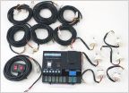 Hideaway strobes
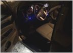 Tacoma Puddle lighting - $30 and a half hour of time - driver and passenger side
 Just got these in the mail!
 Newbie! Need recommendations for lights.
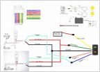
Cheap 4X4 Switch Illumination - Step By Step Write-up
Discussion in 'Lighting' started by Scooter, Jan 9, 2010.
Page 1 of 3
Page 1 of 3


