

-
Welcome to Tacoma World!
You are currently viewing as a guest! To get full-access, you need to register for a FREE account.
As a registered member, you’ll be able to:- Participate in all Tacoma discussion topics
- Communicate privately with other Tacoma owners from around the world
- Post your own photos in our Members Gallery
- Access all special features of the site
 Rear diff gear oil for 11 TRD Sport
 Auto to manual swap progress
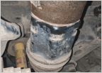 Help - New Leak
 2008 Tacoma door sill protectors
 Fake alarm flashing light, sub 20$, about dodges three times
Manual locking hub
Discussion in '2nd Gen. Tacomas (2005-2015)' started by calleboy, Mar 1, 2016.
Page 7 of 10
Page 7 of 10


