

-
Welcome to Tacoma World!
You are currently viewing as a guest! To get full-access, you need to register for a FREE account.
As a registered member, you’ll be able to:- Participate in all Tacoma discussion topics
- Communicate privately with other Tacoma owners from around the world
- Post your own photos in our Members Gallery
- Access all special features of the site
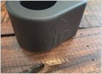 What is this behind my rear seat?
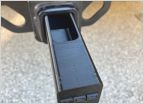 Favorite way to hide a key?
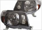 Which Aftermarket Headlights??
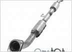 Do aftermarket Catalytic converters ever work
 Oil filter.
Power sliding window mod info thread
Discussion in '2nd Gen. Tacomas (2005-2015)' started by excorcist, Jan 6, 2017.
Page 6 of 13
Page 6 of 13
Products Discussed in


