1. Welcome to Tacoma World!

    You are currently viewing as a guest! To get full-access, you need to register for a FREE account.

    As a registered member, you’ll be able to:
    • Participate in all Tacoma discussion topics
    • Communicate privately with other Tacoma owners from around the world
    • Post your own photos in our Members Gallery
    • Access all special features of the site

Wiring LEDs in Front Light Bar, Rock Lights, Puddle Lights, Rear, Footwell, Bed, Map and Dome

Discussion in 'Lighting' started by pc3coyote, Nov 18, 2017.

  1. Nov 18, 2017 at 6:40 AM
    #1
    pc3coyote

    pc3coyote [OP] www.pc3coyote.com

    Joined:
    Sep 28, 2014
    Member:
    #139276
    Messages:
    1,625
    Gender:
    Male
    First Name:
    Paul
    SoCal
    Vehicle:
    17 BBP Sport DCSB 4x4
    Hello, friends!

    I decided to compile all of my electrical write-ups in one thread.

    This write-up includes:
    • LED front light bar
      • activated by physical switch
    • LED rock lights
      • activated by physical switch AND dome light signal (approaching vehicle, unlocking vehicle, opening doors, etc)
    • LED puddle lights
      • activated by dome light signal (approaching vehicle, unlocking vehicle, opening doors, etc)
    • LED reverse lights
      • activated by physical switch AND stock reverse signal
    • LED footwell lights
      • activated by rock lights physical switch AND dome light signal (approaching vehicle, unlocking vehicle, opening doors, etc)
    • LED bed lights
      • activated by physical switch
    • LED map and dome lights
      • activated by factory physical switch AND dome light signal (approaching vehicle, unlocking vehicle, opening doors, etc)
    Note: this is how I did it and I'm not the best electrically. It seemed like the most logical way but there could definitely be better approaches.

    Huge thanks to @DSIM and @MESO for coming up with great products (referenced below in the rock lights and puddle lights sections) and for all of the help answering my relentless questions. They are great dudes!

    Parts List
    Wiring Diagrams
    • Front Light Bar
      • [​IMG]
    • Rock Lights
      • [​IMG]
    • Reverse Lights
      • [​IMG]
    • Footwell Lights
      • [​IMG]
    • @DSIM Dome Light Harness
    • Switches
    Front Light Bar

    Instructions

    1. Leave the main connections (battery positive and ground) connections for the end once you have all your wires routed as a precaution. Always start with negative battery terminal disconnected (use a 10mm socket) and cover terminal with a rag so it can't make contact.
    2. Remove the grill. Use the phillips screwdriver to remove the two screws and the flat head screwdriver to remove the two plastic tab screws. Grab the upper supports and pull straight out. The plastic tabs will come out.
    3. Remove the wind deflectors on each side. Use the flat head screwdriver to remove the single plastic tab screw on each side.
    4. Remove the two transmission cooler bolts by using the 12mm deep socket. Push the transmission cooler back to make it easier to slide the LED light bar in.
    5. Remove the two nuts on each of the outer sides of each crash bar with the 14mm deep socket. Leave the inner bolts alone. Install only the driver side light bar bracket but only hand-tighten the nuts.
    6. Slide in the light bar from the passenger side to the driver side. Let it rest on the crash bars. Install the passenger side bracket and hand-tighten the nuts. Use the smaller bolts that came with the light bar to attach the light bar to the brackets with a 5mm allen key. I also added two hardened washers (one on each side) but they likely aren’t needed. You may need a second person to hold the light bar as you bolt the light bar to the bracket so that you can lean down to see through the grill to line up the bolts and holes. Ensure that the light bar is pulled all the way forward and rotated to face straight out.
    7. Mount the relay to the bracket by the battery by temporarily removing the bolt with a 10mm socket.
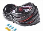
      1. Cut off the spade terminals from the white and black wires from the harness, cut it shorter to length, and use the 14 AWG butt connectors to connect it to the red and black light bar wires (white to red, black to black). Use electrical tape over the connectors. Use electrical tape over the second set of white and black wires from the harness or cut them off if you don't plan to use them (they are for a second light bar).
    8. Temporarily run the two red terminals to the positive battery terminal and the two black terminals to the ground to the right of the relay to test the light bar. Use the attached switch. If it works, disconnect the terminals. If it doesn’t, troubleshoot. The battery terminal requires a12mm socket and the ground requires a 10mm socket.
    9. Reinstall the transmission cooler
    10. Cut off small corners of the wind deflectors with a dremel and then reinstall. This is so that it doesn’t hit the light bar.
    11. Zip tie the wire going from the light bar to the relay in various places to keep it out of the way. There are plenty of places to attach too.
    12. Follow @moe2o4 ’s guide to disassemble the dash panels. Use trim removal tool, 10mm socket, and phillips screwdriver to remove three trim pieces on driver side.
      1. If you're only installing one switch: Remove the blank switch place-holder from the far right. It unclips from the back and pushes to the front.
      2. If you're installing multiple switches: Remove the cubby with a screwdriver.. It unscrews from the back. Screw in the new switch holder.
    13. Cut off the switch from the harness. Cut off a straight piece of a metal hangar. Use the hanger wire to poke a hole in the rubber firewall. Use electrical tape to tape the red, white, and black wires coming from the relay to the hanger. Rub a dab of dish soap over the taped area of the hangar and then pull it through from the interior by pulling on the end of the hangar.
    14. Wire the switch to the harness wires by using the 20 AWG butt connectors. Red harness wire goes to the green switch wire, white harness wire goes to the red 1 (first after green) switch wire, black harness wire goes to the black switch wire. After that, use the 20 AWG quick splice to connect the red 2 (second after green, first from black) switch wire to the green cargo wire (first wire on the first switch from the left). After you connect everything, wrap all the connects in electrical tape.
    15. Reconnect the two two red terminals to the positive battery terminal and the two black terminals to the ground to test the light bar. By default, nothing is lit up. The switch text LED should light up when the interior lights are on. The switch light bar LED should come on when pressed. Test the new switch to make sure it works, that the lighter comes on, and the switch light bar LED should also light up. If it works, proceed. If it doesn’t, troubleshoot.
    16. Ziptie the extra slack going from the relay to the firewall, from the firewall to the battery positive terminal, and from the firewall to the ground terminal. Reinstall the dash panels. Reinstall the grill.
    Photos

    [​IMG]

    [​IMG]
    [​IMG]
    [​IMG]
    [​IMG]

    Rock Lights

    Instructions

    1. Engine bay wiring
      1. Always start with negative battery terminal disconnected (use a 10mm socket) and cover terminal with a rag so it can't make contact.
      2. Run two power wires and two ground wires (for relay and switch) to battery and ground in side of engine bay using 12mm and 10mm socket respectively. Trim to right lengths utilizing 18AWG wire and butt connectors (heat shrunk with lighter, wrapped in electrical tape) as needed. Use wire loom (electrical tape on ends) over wires
      3. Cut off switch. Use a sharp object (coat hanger, shish kabob stick, etc) to poke a hole in the rubber boot, with the switch wire electrical taped to it, to run the switch wire into the cab. Use wire loom to cover wire
    2. Switch placement and wiring
      1. Follow @moe2o4 ’s guide to disassemble the dash panels. Use trim removal tool, 10mm socket, and phillips screwdriver to remove three trim pieces on driver side.
        1. If you're only installing one switch: Remove the blank switch place-holder from the far right. It unclips from the back and pushes to the front.
        2. If you're installing multiple switches: Remove the cubby with a screwdriver.. It unscrews from the back. Screw in the new switch holder.
      2. Push in switches
      3. Use butt connectors (and electrical tape) to connect switch wires to switch
      4. Use quick splice connector (and electrical tape) to connect switch wire to another switch wire for illumination
      5. If you want the rock lights triggered by the dome light signal in addition to the physical switch (approaching vehicle, unlocking vehicle, opening doors, etc
        1. Follow this Toyota guide on removing the a-pillar cover
        2. Ziptie @DSIM relay to one of the factory harnesses
        3. Follow @Volksparts guide on wiring in the @DSIM black wire. Feed @DSIM black wire up behind dash towards a-pillar and use quick splice connector to connect @DSIM black wire to yellow a-pillar wire
        4. Use quick splice connectors to connect @DSIM red wire to switch green wire and @DSIM yellow wire to switch red 1 wire
      6. Reassemble
    3. Lights placement
      1. Rear two lights were under the bumper and were ziptied to the frame
      2. Front two lights were under the front bumper. I made a paper template of the light by tracing it and used that to drill three holes (two mounting bolts and wire) into the flimsy plastic in the front of the truck under the bumper in front of the wheel well. I then mounted the lights using the two supplied bolts. I accessed the inside of the wheel well to secure the 10mm nut from the wheel well using the 10mm socket to hold the nut and the 5mm alley key to tighted the bolt. You access the wheel well by removing one 10mm bolt with the 10mm socket and one push screw with a flathead screwdriver from inside the wheel well and then pull the plastic aside.
      3. Middle lights are on the inside of the body right above the pinch weld. I cleaned the area with a rag and some rubbing alcohol. I centered the lights off of my sliders which end right before and after the front and rear doors respectively but you can center them off other identifiers. My sliders are 78" and the LEDs are 60" so I marked off 9" on the body off the front and back of the sliders for the start and stop points of the LED strips. They are adhesively-backed so applying them is very easy, just firmly press them into into place as you work your way down. (thanks to @KTJO 4x4 for the recommendation of this mounting location)
      4. These are all high enough and protected to not get damaged from offroading
    4. Lights wiring
      1. There are two wires from the relay for each side, each with two leads
      2. Run one wire across back of engine bay facing cab ziptieing to existing harness as you go
      3. Cut off wiring harness leads for the rock light harness. Connect additional wire to one of the harness wire leads with butt connectors (and electrical tape, wrapped in wire loom) and run straight down to under truck
      4. Cut off the ends for the two LED strip lights and set aside the included harness (won't be used)
      5. Run wire to first light (in wire loom) at the passenger front door ziptieing to existing harness as you go
      6. Three way splice with two butt connectors (one for red positive wire and one for black negative wire). One side has the incoming wire. Other side has rock light wire twisted together with additional wire. I'd strip the wire for both the rock light and outgoing wire and then twist the strands together (do that for both red and black wires respectively). Wrap in electrical tape and then put in wire loom
      7. Repeat above for passenger LED strip, passenger rear bumper, driver rear bumper, and finally the driver LED strip (daisy chaining as you go with three way splice at each light, covering wire in wire loom as you go, ziptieing to existing harness as you go)
      8. For the passenger front bumper, connect additional wire (with butt connectors) to the other lead from where you ran across the engine and where you ran the one lead down to under the truck, wrap in wire loom, and fish the wire down to the small opening in the bumper from behind the headlights. Connect the light to the wire and then push all of the extra wire back into the bumper
      9. For the driver front bumper, you can now use the other primary wire coming from the relay. We'll only need the long lead so you can either cut off the extra one in the middle or just cover it electrical tape. Repeat process above for fishing the wire and connecting the light
    [​IMG]
    [​IMG][​IMG][​IMG][​IMG][​IMG][​IMG]
    [​IMG]
    [​IMG][​IMG][​IMG][​IMG][​IMG][​IMG][​IMG][​IMG][​IMG]


    @DSIM dome light harness
    [​IMG]

    Photos

    [​IMG]
    [​IMG]

    Puddle Lights

    [​IMG]
    [​IMG]

    Instructions

    PDF version of instructions: here

    Removing the Door Panels

    1. Disconnect negative battery terminal with 10mm socket
    2. Remove felt in cubby with pick
      1. [​IMG]
    3. Remove plastic behind door handle with pick
      1. [​IMG]
    4. Remove three fasteners securing door panel
      1. [​IMG]
    5. Remove two Phillip screws
      1. [​IMG]
      2. [​IMG]
      3. [​IMG]
      4. [​IMG]
    6. For the plastic insert, push the center button in and then pry outside with pick
      1. [​IMG]
      2. [​IMG]
    7. Remove the upper mirror trim piece with trim removal tool
      1. [​IMG]
    8. Remove door panel with trim removal tool starting at the bottom pulling hard and sliding up towards the window
      1. [​IMG]
    9. Slide out two door handle cables
      1. [​IMG]
    10. Disconnect the two electrical plugs, the larger one has a release tab you press down and a collar that slides back, the smaller one has a release tab you press down,
      1. [​IMG]
      2. [​IMG]
    11. Set door panel aside
      1. [​IMG]
      2. [​IMG]
    12. Repeat Steps 2-11 for the passenger side
      1. Passenger door has two electrical plugs to disconnect as well but both just have a release tab you press down
    Installing the Puddle Lights
    1. Disconnect mirror plug
      1. [​IMG]
    2. Remove three black tape pieces covering the bolts securing the mirror with pick
      1. [​IMG]
    3. Remove three nuts off the mirror bolts passing through the door with a 10mm socket while holding the mirror on the outside of the door so it doesn't fall
      1. [​IMG]
    4. Remove the mirror from outside the door by sliding the bolts through the door once the nuts have been removed
    5. Disconnect the 10” extension from the meso harness
    6. Remove the tape on the mirror cable pass-through
      1. [​IMG]
    7. Remove lower mirror trim piece with pick
      1. [​IMG]
    8. Fish 10” extension through mirror trim piece and then through mirror arm
      1. [​IMG]
      2. [​IMG]
    9. Connect the extension to the puddle light and snap it into place
      1. [​IMG]
      2. [​IMG]
    10. Pull out slack of cords and push the trim piece flush onto the mirror
    11. Rewrap the cables coming out of the pass-through with electrical tape
      1. [​IMG]
      2. [​IMG]
    12. Reinstall mirror from outside door with 10mm socket to reinstall the nuts onto the bolts while passing the cords through the door and holding the mirror in place
      1. [​IMG]
      2. [​IMG]
    13. Repeat Steps 1-12 for passenger side
      1. If the passenger pod does not sit flush, use a pair of snips or a dremel to remove a notch in the plastic so there is clearance for the new light. Not all trucks will have this extra plastic "rib" inside on the passenger side.
      2. [​IMG]
      3. [​IMG]
    Installing the Harness Leads
    1. Overall wiring
      • [​IMG]
      • [​IMG]
    2. Remove floormat
    3. Remove lower kick panel trim piece with tool
      1. [​IMG]
    4. Remove twist cap nut with your hand and then pull side footwell panel trim piece out
      1. [​IMG]
    5. Disconnect three plugs in the driver footwell
      1. [​IMG]
    6. Between the door and the cab, pop off boot from door with pick careful not to hit wires by slowly prying around the edge
    7. Pop off boot from the cab side by prying on around the edge on the outside with the pick and pushing from inside the cab and cut the electrical tape securing the open end of the boot that goes into the cab
      1. [​IMG]
      2. [​IMG]
    8. Take the shorter lead side of the meso harness and add some tape around the extension connector and its wires (if required) so the wires don’t pull out and so the connector release tab doesn’t snag on the boot as you push it through
      1. [​IMG]
    9. Feed the meso cable through the cab passthrough to outside
      1. [​IMG]
    10. Push the connect through the boot which is a little bit of a pain in the butt but have patience, it helps to have one hand stretch the boot as you use the other hand to push the connector through with your finger from the backside of the connector, once you get it more than halfway you can roll the opposite side of the boot back to expose the connector (needle nose pliers may help to grab it) and pull it the rest of the way, be very careful to not rip any of the factory cords or damage the boot
    11. Fish the cable into the door now that you have it through the boot
      1. [​IMG]
    12. Make a small cut in the door plastic lining to reach your hand into the door to pass yourself the meso cable
    13. Pull the cable through and connect it to the end of the extension that's coming through the top of the door
    14. Feed the longer lead side of the meso harness through the small hole of the carpet under the console to the passenger side
      1. [​IMG]
    15. Feed cable under carpet in passenger footwell, it just lifts up
      1. [​IMG]
    16. Repeat Steps 2-13 for the passenger side
      1. There's only two plugs to disconnect for the passenger footwell
      2. [​IMG]
    Installing the Harness to OEM Connections
    1. Remove the three 10mm bolts holding the lower dash piece in place with the 10mm socket
      1. [​IMG]
    2. Gently pull the lower dash piece down to disengage the 11 clips holding it in place
    3. Use the pick to remove the plastic piece in the a pillar that is covering the bolt
      1. [​IMG]
    4. Use the 10mm socket to remove the bolt and pull the a pillar cover off
      1. [​IMG]
    5. Feed the large end of the meso harness behind the dash towards the a pillar
    6. Disconnect the OEM harness and plug the OEM female into the meso male and the OEM male to the meso female, you may need to cut the zip tie securing the OEM harness to do this
      1. [​IMG]
      2. [​IMG]
      3. [​IMG]
    7. Tuck the extra slack of the meso harness in ensuring nothing is getting in the way or possibly interfering with the airbag
      1. [​IMG]
    Final Steps
    1. Reconnect battery negative terminal with 10mm socket
    2. Test by opening and closing your doors and unlocking and locking your doors to ensure the puddle lights come on with the map/dome lights (ensure the map lights switch is set to the center function to be triggered by the door)
      1. [​IMG]
    3. Tape the meso harness to the existing mirror harness in the door
      1. [​IMG]
    4. You can add tape if needed to the plastic lining on the door if you had to cut it to pull the meso extension wire through
    5. Reconnect the door panel electrical plugs and the two cables for the door handle ensuring you snap the ends of the connectors for the door handle wires into the trim on back side of the door panel, the door handle wire connectors have notches for this
    6. Lift the door panel back onto the door starting at the top near the window and sliding down before pressing all of the plastic clips into place
    7. Snap the top mirror trim back into place being careful to not lose the three plastic clips that secure it in the door
      1. [​IMG]
      2. [​IMG]
    8. Screw back the two phillips head screws in the door, the larger screw is for the cubby and the smaller one is for behind the door handle
    9. Snap the plastic insert back into place
    10. Reinstall the felt and plastic trim pieces for the doors
    11. Push the rubber boot back into the door and cab
    12. Repeat Steps 3-10 for the passenger side
    13. Reinstall the a pillar trim piece using the 10mm socket and snapping the cover back over the bolt
    14. Snap the lower dash piece back into place and secure with 10mm bolts
    15. Tuck any extra wiring up behind the lower dash piece and secure with tipties (if required)
    16. Reinstall the side footwell trim piece and tighten with twist nut
    17. Reinstall lower kick panel
    18. Reinstall floor mat
    19. Repeat steps 14-16 for the passenger side
    Photos

    [​IMG]
    [​IMG]
    [​IMG]
    [​IMG]
    [​IMG]
    [​IMG]
    [​IMG]
    [​IMG]
    [​IMG]


    Rear Lights


    Instructions

    1. Same as rock lights with the exception of drilling into the plastic part of the rear bumper with a 1.75" hole saw for the main hole for the light and 3/16" drill bit for the mount screw holes
    2. If you want the new reverse lights to come on with stock reverse signal in addition to physical switch
      1. Follow this EAA guide on how to solder a diode to 2-3 ft of wire and then put wire assembly inside wire loom
      2. Use quick splice connector to connect one end of new wire to middle white wire of trailer harness and other end of new wire to red positive wire of wire leading to the reverse lights
    Photos

    [​IMG] [​IMG] [​IMG] [​IMG]

    Footwell Lights

    Instructions
    1. Always start with negative battery terminal disconnected (use a 10mm socket) and cover terminal with a rag so it can't make contact.
    2. Follow @moe2o4 ’s guide to disassemble the dash panels. Use trim removal tool, 10mm socket, and phillips screwdriver to remove three trim pieces on driver side.
    3. If your LEDs have a control box, mount it in desired location. I mounted mine using the supplied double-sided tape in the driver footwell area in the bottom right corner.
    4. Use a quick splice connector to connect the red positive wire from the LED control box to the yellow @DSIM wire. I also added extra electrical tape around the plastic connectors with the fuse to ensure it doesn't come disconnected.
    5. Use a quick splice connector to connect the black negative wire from the LED control box to the black wire from the rock light CH4x4 switch.
    6. Pass two of the light bars through the small hole of the carpet under the console to the passenger side.
    7. Run two of the light bars (one for each side) to under the seats while tucking the extra wire up and under the side of the wire console.
    8. Secure light bars in desired locations using zipties and/or double-sided tape. I mounted mine at:
      1. Driver side front: under dash with double-sided tape
      2. Passenger side front: under dash with zipties using holes already in dash
      3. Driver side rear: under front of driver seat using zipties around metal support bar
      4. Passenger side rear: under front of passenger seat using zipties around metal support bar

    [​IMG]

    Photos


    [​IMG] [​IMG] [​IMG] [​IMG] [​IMG]

    Switches

    Photos

    Three-switch option

    [​IMG]


    One-switch option


    Relay Holder

    Instructions
    1. This is only if your relays don't have the empty tab slot on the back to install onto the relay holder
      1. Drill three holes into relay holder tabs to mount relays with zipties. If you buy relays from an auto parts store, they'll have a slot where the relay holder tabs will slide in. Since I used premade harnesses, they didn't have this
      2. Spray paint over the new holes to avoid rust
      3. Mount relay holder in engine bay
      4. Install relays on relay holder with zipties through hole in the relay and new holes in the relay holder
    Bed Lights

    Instructions

    1. Follow @mattgecko's instructions which are really easy to follow, you'll receive them with your order
    Photos

    [​IMG]
    [​IMG]
    [​IMG]

    Map and Dome Lights

    Map Lights Instructions

    [​IMG]

    Dome Light Instructions

    • From Toyota, the switch's two positions are 'always on' and 'on with doors'. There is no way to have it off when the doors are open unless you also have the map lights turned off as well. The door trigger disconnect mod for the dome light allows for independent control of the dome light with the switch without dome light coming on with the doors.
    • Disconnect negative side of the battery with a 10mm socket just to be safe.
    • Gather tools. If you're just installing it normally (come on with doors open as well as the switch), you only need a small screwdriver like below. If you're doing the door trigger disconnect, you'll also need some and a lighter or heat gun.
      • [​IMG]
    • Use the screwdriver to remove the stock plastic cover by inserting it into the slots circled in green on the switch side. There are four blue tabs that will come out of the black housing.
      • [​IMG]
    • Remove the stock bulb. If you are not doing the door trigger disconnect, you can skip to the end. If you are doing the door trigger disconnect, use the screw driver to push back the two tabs circled in green below in the black housing. Then use your fingers and slowly start pulling the dome light housing down from each corner. There are a few clips holding it in but it will give once you pull on it lightly.
      • [​IMG]
    • Once you have it disconnected, insert the screwdriver into the little slots circled in blue, there are two small tabs for the grey piece that you are unclipping. You can use your finger to push the grey section out as you do this.
      • [​IMG]
    • Here is the back of the black housing. The location of the two tabs that you were undoing above are circled below in blue. Once they are unclipped, that side of the grey piece unclips and pulls out from the black housing.
      • [​IMG]
    • Once you separate the grey piece from the black housing, you need to expose the wires. Use the screwdriver to lightly push each of the four tabs below circled in green to remove the cover over the wires. You can also use your finger from the side to help pry the lid off.
      • [​IMG]
    • Once you have the cover off, use your fingers or the screwdriver to lightly pull up the middle red wire leaving the two side wires in place. Cut off a small piece of heat shrink, insert it over the red wire, and use a lighter or heat gun to shrink it. Set it off to the side away from where the wire cover goes.
      • [​IMG]
      • [​IMG]
    • Snap the wire cover back on over the wires. You then reinstall the grey piece back into the black housing. Insert the side with the wires that goes towards the switch in first (circled below in green) and then snap it into place with a light push.
      • [​IMG]
      • [​IMG]
    • Push the black housing back into the headliner. Make sure you fully press each corner until it's sitting tight and flush into the headliner. Now, you can install the new meso dome light. Lightly squeeze the bulb adapter and while compressed insert it into the spot of the stock bulb and then release. The red positive wire goes toward the driver side.
      • [​IMG]
      • [​IMG]
    • Install the new cover starting with the back side with the larger two plastic tabs. You can tuck the wire in behind the light, just make sure that it doesn't stick out of the slot where the switch goes. You can give it a light squeeze as you push in the front two tabs.
      • [​IMG]
      • [​IMG]
    • Reconnect negative side of the battery with a 10mm socket.
    • Test it out! One side of the switch should be always off and the other side should be always on. You can now have the dome light come on whenever you want and have it off with the doors open so that only the map lights come on with the doors open.
    Photos

    [​IMG] [​IMG] [​IMG] [​IMG] [​IMG] [​IMG] [​IMG] [​IMG]
     
    Last edited: May 30, 2019
    Mudman, Danbest82, Emc2 and 34 others like this.
  2. Dec 13, 2017 at 7:45 PM
    #2
    pc3coyote

    pc3coyote [OP] www.pc3coyote.com

    Joined:
    Sep 28, 2014
    Member:
    #139276
    Messages:
    1,625
    Gender:
    Male
    First Name:
    Paul
    SoCal
    Vehicle:
    17 BBP Sport DCSB 4x4
    Updated OP with instructions and photos from rock light install!
     
  3. Dec 13, 2017 at 7:52 PM
    #3
    20tacoma17

    20tacoma17 Well-Known Member

    Joined:
    Nov 8, 2016
    Member:
    #201910
    Messages:
    7,095
    Gender:
    Male
    Vehicle:
    2017 DCLB Sport AT
    Kings, 275/70/17, a few custom items, lots of Meso mods.
    Nice write-up and those are plenty bright.
     
    pc3coyote[OP] likes this.
  4. Dec 13, 2017 at 7:59 PM
    #4
    Sandman614

    Sandman614 Ex-Snarky TWSS elf, Travis #hotsavannahdotcom

    Joined:
    Oct 26, 2010
    Member:
    #45273
    Messages:
    35,565
    Gender:
    Male
    First Name:
    Tim
    Garner, NC/Boone, NC
    Vehicle:
    '06 SR5 Off Road
    ARB Front Bumper, Projector Headlights w/Slimcubby 4300K HID's, Oznium LED's, LED taillights, DIY Washable Cabin Moose Filter, Sockmonkey SR5 Off Road, Aux Audio plug, OME 886x, OME Nitrochargers, Wheelers 3 Leaf Progressive AAL, ImMrYo Rear-View Mirror Lift Bracket, Dodge D-Rings
    The only thing I'm laughing at is your use of the words Rock Lights and the fact you zip tied them to the frame. Underglow would be a more accurate term for this installation.

    Otherwise I like the pics and arrows. Bonus points for proper diagrams.
     
    corgimas and 9TRDTCO like this.
  5. Dec 13, 2017 at 8:03 PM
    #5
    pc3coyote

    pc3coyote [OP] www.pc3coyote.com

    Joined:
    Sep 28, 2014
    Member:
    #139276
    Messages:
    1,625
    Gender:
    Male
    First Name:
    Paul
    SoCal
    Vehicle:
    17 BBP Sport DCSB 4x4
    Thanks! I didn't plan to do a write-up for this one or I would have taken better pics as I installed it. I figured it may be useful others not as mod-savvy like myself so I did it from memory after the fact.

    edit: I've since updated my installation to remove the pod lights under the cab and installed LED strips. This was after I started doing a lot more offroading and realized the pods under the frame and sliders wouldn't last long. Now all lights are safe! I think I can safely call them rock lights again versus underglow lights :D

    [​IMG]
     
    Last edited: Sep 9, 2018
  6. Dec 14, 2017 at 7:23 AM
    #6
    jzh11

    jzh11 Well-Known Member

    Joined:
    Jun 30, 2017
    Member:
    #222783
    Messages:
    64
    Orlando, FL
    Vehicle:
    17 SR5 DCSB
    I wonder if you wired the undercarriage lights to the cargo lamp it would come on when you hit the unlock button. They would definitely come on when you opened the door at least and you'd already have the stock button to use. Can anyway chime in? I'm very interested

    Edit - awesome job btw

    Edit edit - I just went and double checked...the cargo lamp does come on when you hit the unlock button so I don't see why that wouldn't work
     
    pc3coyote[OP] likes this.
  7. Dec 14, 2017 at 7:38 AM
    #7
    pc3coyote

    pc3coyote [OP] www.pc3coyote.com

    Joined:
    Sep 28, 2014
    Member:
    #139276
    Messages:
    1,625
    Gender:
    Male
    First Name:
    Paul
    SoCal
    Vehicle:
    17 BBP Sport DCSB 4x4
    Thanks!

    Yeah, having it wired to the dome light would make it so that the rock lights come on when you unlock the truck and approach the truck with a key (just like the dome and map lights).

    I wasn’t sure where to tap into the dome light circuit, where to tap into my new wiring I did, and where to add a diode if it’s needed. Also the dome light circuit fades on/off and relays don’t like that I don’t think. You’ll hear it chattering and it’ll eventually kill it (again I think). I was definitely considering adding that to all of this but I wasn’t sure how to execute it.
     
    jzh11[QUOTED] likes this.
  8. Dec 14, 2017 at 7:50 AM
    #8
    jzh11

    jzh11 Well-Known Member

    Joined:
    Jun 30, 2017
    Member:
    #222783
    Messages:
    64
    Orlando, FL
    Vehicle:
    17 SR5 DCSB
    I was thinking of the cargo lamp facing the bed of the truck. I don't believe that one fades out. it just shuts off. I could be wrong
     
  9. Dec 14, 2017 at 9:46 AM
    #9
    pc3coyote

    pc3coyote [OP] www.pc3coyote.com

    Joined:
    Sep 28, 2014
    Member:
    #139276
    Messages:
    1,625
    Gender:
    Male
    First Name:
    Paul
    SoCal
    Vehicle:
    17 BBP Sport DCSB 4x4
    Ah okay! Hmm that could work! I’m all for this if we can figure it out haha
     
    jzh11[QUOTED] likes this.
  10. Dec 24, 2017 at 7:54 PM
    #10
    swtaco10

    swtaco10 Well-Known Member

    Joined:
    Feb 7, 2016
    Member:
    #177425
    Messages:
    232
    Gender:
    Male
    First Name:
    Dave
    South of Tampa
    Vehicle:
    2010 Tacoma TRD off-Road
    Bilstein 5100's, LED interior and puddle lights, 17" XD revolver's, Grabber A/T2's
    I utilized the dome light circuit by taping into the wire behind the a-pillar. Mine fades in and out with the dome light, key fob and all. But with mine being a 2010 the wiring could be all different. My girlfriend's Camry has the same wiring for her underglow light.
     
    pc3coyote[OP] likes this.
  11. Dec 26, 2017 at 12:05 PM
    #11
    redrelyt12

    redrelyt12 Well-Known Member

    Joined:
    Mar 29, 2016
    Member:
    #182753
    Messages:
    758
    Gender:
    Male
    First Name:
    Tyler
    Vehicle:
    2016 Tacoma TRD Sport DCLB
    Derped TRD Sport Grille BAK Revolver X2 Tonneau Cover mattgecko Waterproof LED Hood & Bed light kits Southern Style OffRoad Slimline Hybrid Front Bumper Baja Designs 20" S8 Light Bar Smittybilt X2O-10 Winch Blue 3/4" Shackles
    Did you figure this out? When I installed the @mesojdm LED Bed Lights, I followed the Toyota Instructions for their LED Bed Lights (P/N: 00016-34089). Page 7 lists plug the (+) into the Light Green wire of the IE1 connector, and the ground into the White wire of the IA connector. I followed these instructions and now my Bed Lights turn on when the cargo light goes on.

    As for the reverse lights, my recommendation would be to splice into the wiring going into the tail light assembly.

    One thing to note, there may be some back-feed where your reverse lights/cargo light would turn on when you flip the switch in the cab.
     
  12. Dec 26, 2017 at 3:33 PM
    #12
    pc3coyote

    pc3coyote [OP] www.pc3coyote.com

    Joined:
    Sep 28, 2014
    Member:
    #139276
    Messages:
    1,625
    Gender:
    Male
    First Name:
    Paul
    SoCal
    Vehicle:
    17 BBP Sport DCSB 4x4
    I have not. I haven’t had a chance to fiddle with this further with the holidays.

    I wasn’t sure which of the new wires to use to tap into the factory harnessing and where. I believe you can use diodes to eliminate any back-feed. Eventually I’ll play with this more. I am a little uneasy about causing problems by tapping into the factory stuff mainly because I am not too knowledgeable about the electrical stuff.
     
  13. Jan 11, 2018 at 8:16 PM
    #13
    Doc V

    Doc V Well-Known Member

    Joined:
    Jan 31, 2016
    Member:
    #176743
    Messages:
    94
    Gender:
    Male
    Caldwell, ID
    Vehicle:
    2013 Tacoma Double Cab Short Box
    Rear seat 12V Outlets Streamlight Flashlight Install Remote Start Bed lights Amber emergency lighting Aries Grille Guard ARE topper with ski-rack USB power point
    Great write up first off and I appreciate you thinking of cheap rock lights and making the assumption that they will break. Did you end up going with a relay or a diode for the reverse light? I am torn on whether to use a SPDT relay or a diode to restrict back-flow from with the reverse lights. I wanted to confirm before I get under the truck in the cold! Thanks man
     
    pc3coyote[OP] likes this.
  14. Jan 13, 2018 at 7:10 AM
    #14
    pc3coyote

    pc3coyote [OP] www.pc3coyote.com

    Joined:
    Sep 28, 2014
    Member:
    #139276
    Messages:
    1,625
    Gender:
    Male
    First Name:
    Paul
    SoCal
    Vehicle:
    17 BBP Sport DCSB 4x4
    I actually haven’t finished the reverse lights yet, I just haven’t had time.

    Either way, I haven’t figured out how to tie them into the reverse light signals yet. I’ll look into it more when I install them. Let me know what you come up with.

    Good luck!
     
    DubfromGA likes this.
  15. Jan 13, 2018 at 7:38 AM
    #15
    Technique

    Technique Well-Known Member

    Joined:
    Nov 4, 2017
    Member:
    #235046
    Messages:
    2,715
    Gender:
    Male
    First Name:
    Alex
    Utah
    Vehicle:
    2017 Silver Offroad DCSB
    -285/70/17 Toyo AT3 -Tuned
    That looks really good. Nice write up!...may look into doing this one of these days. I've been going off-roading at night lately and could use some lights like this instead of a flashlight!
     
    pc3coyote[OP] likes this.
  16. Jan 23, 2018 at 8:55 PM
    #16
    pc3coyote

    pc3coyote [OP] www.pc3coyote.com

    Joined:
    Sep 28, 2014
    Member:
    #139276
    Messages:
    1,625
    Gender:
    Male
    First Name:
    Paul
    SoCal
    Vehicle:
    17 BBP Sport DCSB 4x4
    Thanks! Good luck! Post some pics if you do!
     
  17. Jan 23, 2018 at 8:57 PM
    #17
    pc3coyote

    pc3coyote [OP] www.pc3coyote.com

    Joined:
    Sep 28, 2014
    Member:
    #139276
    Messages:
    1,625
    Gender:
    Male
    First Name:
    Paul
    SoCal
    Vehicle:
    17 BBP Sport DCSB 4x4
    Updated the OP! I finally got around to installing the Rigid rear lights which had been sitting in my garage for two months. I'm really happy with how it came out. Massive pain in the ass to squeeze the lights in without them interfering the license plate lights. It was also damn near impossible to get your hand in the backside of the bumper to get the washer and locknuts on. If I did it again, I'd install them lower on the bottom part of the black plastic of the bumper. They are definitely crazy bright (even with the diffused option I have versus the flood or spot options available).
     
    Last edited: Jan 23, 2018
    redrelyt12 likes this.
  18. Jan 23, 2018 at 9:33 PM
    #18
    outxider

    outxider Never stop exploring. Rest in Paradise Big Bro.

    Joined:
    May 9, 2010
    Member:
    #36858
    Messages:
    2,083
    Gender:
    Male
    First Name:
    Sang
    East Bay, CA
    Vehicle:
    06 DCSB 4x4
    A few mods here and there and counting....
    You can wire the reverse light pods into the stock oem reverse wire either at one of the rear taillights or trailer harness, but will need a diode to prevent back feed so when you hit the switch, the reverse indicator doesn't light up on the dash. I haven't done it but read/watch some videos regarding it. My reverse pods are just tapped into the reverse signal off the trailer harness.
     
    pc3coyote[OP] likes this.
  19. Jan 23, 2018 at 9:36 PM
    #19
    pc3coyote

    pc3coyote [OP] www.pc3coyote.com

    Joined:
    Sep 28, 2014
    Member:
    #139276
    Messages:
    1,625
    Gender:
    Male
    First Name:
    Paul
    SoCal
    Vehicle:
    17 BBP Sport DCSB 4x4
    Thanks!

    Dumb question - would I just run a wire from the positive wire running to the reverse lights to the hot reverse wire of the tail lights (with the diode from the tail lights -> Rigid lights)?

    I've been super apprehensive to screw with the factory stuff haha. All of my lights are currently on relays and independent of the factory harnessing. Only two exceptions are the topper brake light tapped off of the tail light and the illumination for my CH4x4 switches tapped off the interior cargo light switch.
     
  20. Jan 23, 2018 at 11:39 PM
    #20
    outxider

    outxider Never stop exploring. Rest in Paradise Big Bro.

    Joined:
    May 9, 2010
    Member:
    #36858
    Messages:
    2,083
    Gender:
    Male
    First Name:
    Sang
    East Bay, CA
    Vehicle:
    06 DCSB 4x4
    A few mods here and there and counting....
    Correct. The diode would be in place between Truck's Reverse Hot and Rigid lights. Its prevents power from the rigid lights from sending back to the truck's reverse lights. Post it up when you have it done. :thumbsup:

     
    pc3coyote[QUOTED][OP] likes this.
To Top