

-
Welcome to Tacoma World!
You are currently viewing as a guest! To get full-access, you need to register for a FREE account.
As a registered member, you’ll be able to:- Participate in all Tacoma discussion topics
- Communicate privately with other Tacoma owners from around the world
- Post your own photos in our Members Gallery
- Access all special features of the site
 Bad Battery? Tested for Parasitic Draw, Different Battery...
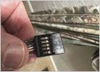 Trick to Pulling Pins from Gen2 4wd Switch Plug
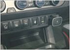 Help wiring Dual USB Port Charger
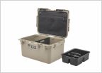 Alternative to Yeti LoadOut box for recovery gear?
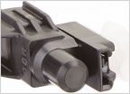 Compass & Thermometer Retrofit
DIY - Build and install a Bussmann RTMR Fuse/Relay Block
Discussion in 'Technical Chat' started by tacozord, Nov 4, 2015.
Page 26 of 70
Page 26 of 70
Products Discussed in


