

-
Welcome to Tacoma World!
You are currently viewing as a guest! To get full-access, you need to register for a FREE account.
As a registered member, you’ll be able to:- Participate in all Tacoma discussion topics
- Communicate privately with other Tacoma owners from around the world
- Post your own photos in our Members Gallery
- Access all special features of the site
 Viair vs ARB compressors
 Where do i put my transmission temp sensor
 Exterior Paint Sealant or Carnuba Wax?
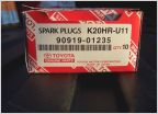 How To: Spark Plug Change (1 GR-FE)
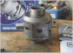 Just Installed a Powertrax No Slip AKA Lunchbox Locker in my 2nd gen
The NorthStar AGM Battery + Voltage Booster Upgrade
Discussion in 'Technical Chat' started by crashnburn80, Apr 14, 2019.
Page 5 of 67
Page 5 of 67
Products Discussed in


