-
Welcome to Tacoma World!
You are currently viewing as a guest! To get full-access, you need to register for a FREE account.
As a registered member, you’ll be able to:- Participate in all Tacoma discussion topics
- Communicate privately with other Tacoma owners from around the world
- Post your own photos in our Members Gallery
- Access all special features of the site
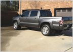 New Truck
 Who line-x their bed?
 Rear driveshaft U-Joints
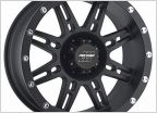 Ordering new wheels. What else do I need?
 My solution to Behind the seat storage (with molle panel)
 255's :255/85/R16 or 255/80/R17, what fits the 2nd Gens?
(MOD) Hazard switch & Passenger airbag/belt indicator LED color.
Discussion in '2nd Gen. Tacomas (2005-2015)' started by mctechhweng, Jan 7, 2019.