

-
Welcome to Tacoma World!
You are currently viewing as a guest! To get full-access, you need to register for a FREE account.
As a registered member, you’ll be able to:- Participate in all Tacoma discussion topics
- Communicate privately with other Tacoma owners from around the world
- Post your own photos in our Members Gallery
- Access all special features of the site
 More headlight questions
 Anyone try these?
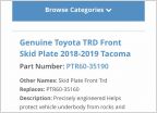 TRD Skid where to buy
 Go Pro Mount
 Slow open tailgate broke. IS my part number correct?
 Official Toyota Stop Sale on 2017 TRD Pro Parts
Wiring Help
Discussion in '3rd Gen. Tacomas (2016-2023)' started by mrmojorisingi, Jul 6, 2019.
Page 1 of 2
Page 1 of 2

