

-
Welcome to Tacoma World!
You are currently viewing as a guest! To get full-access, you need to register for a FREE account.
As a registered member, you’ll be able to:- Participate in all Tacoma discussion topics
- Communicate privately with other Tacoma owners from around the world
- Post your own photos in our Members Gallery
- Access all special features of the site
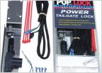 Which tail gate lock?
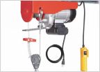 Rtt garage hanging solution?
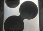 Center console mask
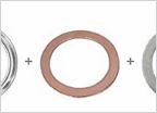 Transfer-case and Diff gaskets
 Knock Sensor Replacement
 Good Caliper Spreaders for 2Gen Taco?
Help wiring a new voltmeter. Can I use the wires from the cigarette lighter / powerpoint harness?
Discussion in '2nd Gen. Tacomas (2005-2015)' started by kevinludlow, Jul 29, 2019.
Page 1 of 2
Page 1 of 2

