-
Welcome to Tacoma World!
You are currently viewing as a guest! To get full-access, you need to register for a FREE account.
As a registered member, you’ll be able to:- Participate in all Tacoma discussion topics
- Communicate privately with other Tacoma owners from around the world
- Post your own photos in our Members Gallery
- Access all special features of the site
 Ok to top off front dif w/ Valvoline?
 UltraGauge 1st Gen ABS Issue Fix
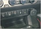 Help wiring Dual USB Port Charger
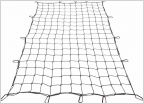 Mesh cover. short box
 6 speed shenanigans. RA60F swap to RC62F
 Any Thoughts On This?
Ken the electrical guy Q n A
Discussion in 'Technical Chat' started by Kens04Taco, Oct 8, 2019.
Page 21 of 36
Page 21 of 36