

-
Welcome to Tacoma World!
You are currently viewing as a guest! To get full-access, you need to register for a FREE account.
As a registered member, you’ll be able to:- Participate in all Tacoma discussion topics
- Communicate privately with other Tacoma owners from around the world
- Post your own photos in our Members Gallery
- Access all special features of the site
 Recovery hook question
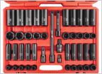 God I Hate Incomplete Tool Sets
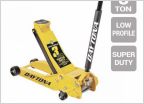 What jack do you use?
 Replacement Horn For 2019 Rav4
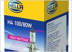 Looking for more light output?
DIY Spod/switchpro fuse relay panel
Discussion in 'General Automotive' started by Matmo215, May 13, 2020.
Page 1 of 2
Page 1 of 2
Products Discussed in


