

-
Welcome to Tacoma World!
You are currently viewing as a guest! To get full-access, you need to register for a FREE account.
As a registered member, you’ll be able to:- Participate in all Tacoma discussion topics
- Communicate privately with other Tacoma owners from around the world
- Post your own photos in our Members Gallery
- Access all special features of the site
 2019 Offroad all LED upgrade
 Aftermarket wireless charger replacement
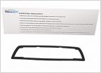 Toyota Recall on 3rd light gasket issue
 Removing dealer pinstripes - how to?
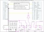 Custom Switch Wiring for Aftermarket Front & Rear Lockers
 Portable air compressor for tires
Ditch Lights & How to get through firewall
Discussion in '3rd Gen. Tacomas (2016-2023)' started by follmer, Aug 23, 2020.


