-
Welcome to Tacoma World!
You are currently viewing as a guest! To get full-access, you need to register for a FREE account.
As a registered member, you’ll be able to:- Participate in all Tacoma discussion topics
- Communicate privately with other Tacoma owners from around the world
- Post your own photos in our Members Gallery
- Access all special features of the site
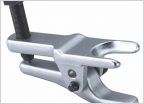 Tie rod end removal (2nd Gen)
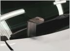 GMRS Radio Antennas - Ground Plane?
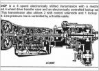 Transmission Aisn Warner 340 series transmissions ( WRITE UP ) Your 4 speed automatic
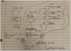 Help With Electrical Layout
 Torque Wrench
Ken the electrical guy Q n A
Discussion in 'Technical Chat' started by Kens04Taco, Oct 8, 2019.
Page 23 of 36
Page 23 of 36