

-
Welcome to Tacoma World!
You are currently viewing as a guest! To get full-access, you need to register for a FREE account.
As a registered member, you’ll be able to:- Participate in all Tacoma discussion topics
- Communicate privately with other Tacoma owners from around the world
- Post your own photos in our Members Gallery
- Access all special features of the site
 Headlight assembly and led/hid conversion
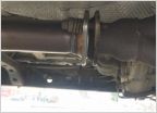 Long lasting muffler in salt country
 Need to wire a plate light
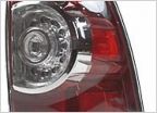 Replace factory taillights on 05 Tacoma w/ LED lights marketed for 2009-2012 models ?
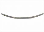 Squeaky dakars!
Oops- I think I made a roof rack
Discussion in '2nd Gen. Tacomas (2005-2015)' started by NeonHeights, Nov 30, 2020.
Page 2 of 7
Page 2 of 7

