-
Welcome to Tacoma World!
You are currently viewing as a guest! To get full-access, you need to register for a FREE account.
As a registered member, you’ll be able to:- Participate in all Tacoma discussion topics
- Communicate privately with other Tacoma owners from around the world
- Post your own photos in our Members Gallery
- Access all special features of the site
Quick Links: 5VZ-FE, 3.4L V6, Detailed Post on Performance Problem. Please, PLEASE Offer Informed Input
 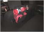 DIY Headrest Fire Extinguisher/Accessory Mount Share Your ARB RD129 Experience
 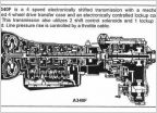 Transmission Aisn Warner 340 series transmissions ( WRITE UP ) Your 4 speed automatic Diff oil recomendation
  IPad for back up camera?
Ken the electrical guy Q n A
Discussion in 'Technical Chat' started by Kens04Taco, Oct 8, 2019.
Page 35 of 36
Page 35 of 36