

-
Welcome to Tacoma World!
You are currently viewing as a guest! To get full-access, you need to register for a FREE account.
As a registered member, you’ll be able to:- Participate in all Tacoma discussion topics
- Communicate privately with other Tacoma owners from around the world
- Post your own photos in our Members Gallery
- Access all special features of the site
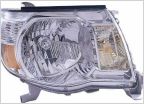 Question about these ebay headlights.
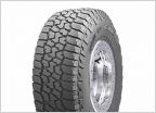 Tires for 2015 Base 4x4 Tacoma
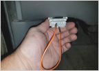 Code 1408 L/R wheel speed sensor options???
 Torn between leaf springs!! Help!!
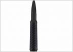 50 Cal Bullet Antenna
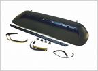 Hood scoop insert
Overhead Compass/Temp Fix
Discussion in '2nd Gen. Tacomas (2005-2015)' started by misc, Nov 9, 2008.
Page 37 of 116
Page 37 of 116
Products Discussed in


