

-
Welcome to Tacoma World!
You are currently viewing as a guest! To get full-access, you need to register for a FREE account.
As a registered member, you’ll be able to:- Participate in all Tacoma discussion topics
- Communicate privately with other Tacoma owners from around the world
- Post your own photos in our Members Gallery
- Access all special features of the site
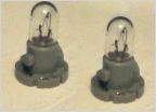 Interior light woes
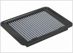 Another air filter question/ need part number
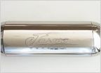 Any ever try a straight pipe with stock cats on a 2nd gen V6 standard?
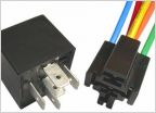 Aftermarket keyless entry wiring
Drive Shaft Vibrations Solved Step-by-Step
Discussion in '2nd Gen. Tacomas (2005-2015)' started by TscotR214, Oct 18, 2012.
Page 54 of 60
Page 54 of 60

