

-
Welcome to Tacoma World!
You are currently viewing as a guest! To get full-access, you need to register for a FREE account.
As a registered member, you’ll be able to:- Participate in all Tacoma discussion topics
- Communicate privately with other Tacoma owners from around the world
- Post your own photos in our Members Gallery
- Access all special features of the site
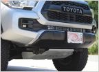 Anyone order an OEM TRD front skid plate?
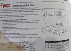 TRD Pro Skid Plate HW
 Can I mix Gear Oil..?
 Issues with the dash display please help I’m stressing here
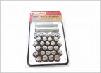 TRD Off Road Beadlock Style wheels
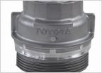 Help, changed oil filter housing(aluminum) and now leaking
DRL (incandescent) on with ignition? 2020 Tacoma SR5
Discussion in '3rd Gen. Tacomas (2016-2023)' started by Clifford20, Sep 6, 2024.
Page 2 of 4
Page 2 of 4


