

-
Welcome to Tacoma World!
You are currently viewing as a guest! To get full-access, you need to register for a FREE account.
As a registered member, you’ll be able to:- Participate in all Tacoma discussion topics
- Communicate privately with other Tacoma owners from around the world
- Post your own photos in our Members Gallery
- Access all special features of the site
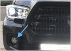 LED Fogs
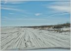 What Do I Need for Beach Driving?
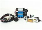 Bed Inverter Wiring for ARB Compressor (CKMA12)
 Looking for Scan Tool Recommendations
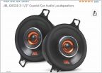 Question about Radio unit and speakers
 Dog Problems and Solutions?
Another Around the World Tacoma
Discussion in '3rd Gen. Tacomas (2016-2023)' started by MR E30, Nov 30, 2021.
Page 27 of 31
Page 27 of 31
Products Discussed in


