

-
Welcome to Tacoma World!
You are currently viewing as a guest! To get full-access, you need to register for a FREE account.
As a registered member, you’ll be able to:- Participate in all Tacoma discussion topics
- Communicate privately with other Tacoma owners from around the world
- Post your own photos in our Members Gallery
- Access all special features of the site
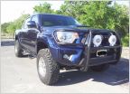 Brush Guard?
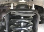 Top hat rubber gasket bulging, Bilstein 6112
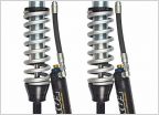 Need help with shock length!
 Camper top front bed seal
 TPMS BS
A340 Paddle Shifters
Discussion in '2nd Gen. Tacomas (2005-2015)' started by SmallerBaller, Dec 3, 2024.
Page 2 of 4
Page 2 of 4


