

-
Welcome to Tacoma World!
You are currently viewing as a guest! To get full-access, you need to register for a FREE account.
As a registered member, you’ll be able to:- Participate in all Tacoma discussion topics
- Communicate privately with other Tacoma owners from around the world
- Post your own photos in our Members Gallery
- Access all special features of the site
 Can't remove splash guard without removing flare, also the opposite?
 Major upgrade
 Raptor lights on 2nd Gen OEM Grill
 Sounds/vibration days after lift.
 Getting New Frame Installed, Por-15 Application?
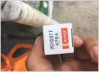 Den so iridium tt plugs?
2nd Gen Tacoma 4.6 V8 1UR-FE and GX powertrain Swap
Discussion in '2nd Gen. Tacomas (2005-2015)' started by dpanibratets, May 22, 2022.
Page 57 of 59
Page 57 of 59
Products Discussed in


