-
Welcome to Tacoma World!
You are currently viewing as a guest! To get full-access, you need to register for a FREE account.
As a registered member, you’ll be able to:- Participate in all Tacoma discussion topics
- Communicate privately with other Tacoma owners from around the world
- Post your own photos in our Members Gallery
- Access all special features of the site
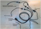 Plug N play harness to relocate USB port.
 Best way to stiffen stock suspension for towing
 T nut sizes?
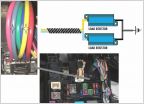 Installed Resister for LED hyper-flashing
 Aerospace 303 for tire appearance....yea or nea?
BSM System Totally Dead - Troubleshooting Woes (2020 Tacoma)
Discussion in '3rd Gen. Tacomas (2016-2023)' started by TacoD0818, Jun 10, 2025.
Page 1 of 2
Page 1 of 2