

-
Welcome to Tacoma World!
You are currently viewing as a guest! To get full-access, you need to register for a FREE account.
As a registered member, you’ll be able to:- Participate in all Tacoma discussion topics
- Communicate privately with other Tacoma owners from around the world
- Post your own photos in our Members Gallery
- Access all special features of the site
 How do ya…?
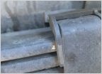 Suspension squeak
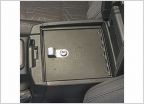
 Installing Dual Fast Charge USB Ports where wireless charge button is
 Embarrassed to ask but Air filter question
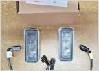 2020 OEM Tacoma bed lights
BSM System Totally Dead - Troubleshooting Woes (2020 Tacoma)
Discussion in '3rd Gen. Tacomas (2016-2023)' started by TacoD0818, Jun 10, 2025.
Page 2 of 2
Page 2 of 2


