-
Welcome to Tacoma World!
You are currently viewing as a guest! To get full-access, you need to register for a FREE account.
As a registered member, you’ll be able to:- Participate in all Tacoma discussion topics
- Communicate privately with other Tacoma owners from around the world
- Post your own photos in our Members Gallery
- Access all special features of the site
 Driver side door clips "HELP"
 2.7L Alternator differences
 Which helper springs
 Silver detailing?
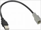 Aftermarket radio
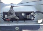 2015 backup camera
Is mechanic right? CEL - P0430
Discussion in '2nd Gen. Tacomas (2005-2015)' started by LilTuffGirl, Jan 18, 2012.