1. Welcome to Tacoma World!

    You are currently viewing as a guest! To get full-access, you need to register for a FREE account.

    As a registered member, you’ll be able to:
    • Participate in all Tacoma discussion topics
    • Communicate privately with other Tacoma owners from around the world
    • Post your own photos in our Members Gallery
    • Access all special features of the site

Input plz - My attempt at diagrams (2)

Discussion in 'Lighting' started by EVErsionDesigns, Jul 10, 2012.

  1. Jul 10, 2012 at 3:33 PM
    #1
    EVErsionDesigns

    EVErsionDesigns [OP] Well-Known Member

    Joined:
    Jul 6, 2011
    Member:
    #59388
    Messages:
    469
    Gender:
    Male
    92374
    Vehicle:
    '11 4wd TRD OffRoad
    Camburg UCA, 2.5" Icons, 2.0" Icon air bumps, TRD Intake, TRD Exhaust, TRD TT Wheels, OMF Beadlocks, BFG
    Lights draw 2.1 amps each
    26.88 watts each
    So 53.76watts and 4.2amps, correct?
    Switch is rated at 20amps

    So will either of these work?

    This one with an in-line fuse
    6c1738b8-ad1a-6a62_f4e20ae16544b4287f021f7d2d63f9d0c2ba04e5.jpg

    This one with an add-a-circuit
    6c1738b8-ad35-441d_495fbecec8276a63fa61de4f23d7424d8dd6040b.jpg

    If I have embarrassed myself please be gentle lol
     
  2. Jul 10, 2012 at 3:37 PM
    #2
    Pugga

    Pugga Pasti-Dip Free 1983 - 2015... It was a good run

    Joined:
    Jun 18, 2010
    Member:
    #39131
    Messages:
    38,444
    Gender:
    Male
    First Name:
    Mike
    Massachusetts
    Vehicle:
    '19 Ford F-250 6.7 SCrew
    F-250 Land Yacht Mod
    Both will work, they're basically the same thing. If I were you though, I'd use a relay and wire the lights so they go off when the ignition is turned off. Depending on which circuit you tap with the Add A Circuit, this could be accomplished.

    Also, the benefit of using a relay is you don't have to run that much power through the switch. Your power would go from the battery, through an in-line fuse, to the relay to the lights. The switch would then only need a tiny bit of power to trip the relay rather than running 4.5 Amps through the switch.
     
  3. Jul 10, 2012 at 4:08 PM
    #3
    EVErsionDesigns

    EVErsionDesigns [OP] Well-Known Member

    Joined:
    Jul 6, 2011
    Member:
    #59388
    Messages:
    469
    Gender:
    Male
    92374
    Vehicle:
    '11 4wd TRD OffRoad
    Camburg UCA, 2.5" Icons, 2.0" Icon air bumps, TRD Intake, TRD Exhaust, TRD TT Wheels, OMF Beadlocks, BFG
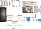
    How's this?
    Seems like overkill.
    Just better to be safe than sorry?

    These are bed lights btw..

    6c1738b8-b66b-994c_e14f628678b7c0d10a36d59bf1e04d199d5ae704.jpg
     
  4. Jul 10, 2012 at 5:21 PM
    #4
    Pugga

    Pugga Pasti-Dip Free 1983 - 2015... It was a good run

    Joined:
    Jun 18, 2010
    Member:
    #39131
    Messages:
    38,444
    Gender:
    Male
    First Name:
    Mike
    Massachusetts
    Vehicle:
    '19 Ford F-250 6.7 SCrew
    F-250 Land Yacht Mod
    First, there's something going wrong between your two diagrams. I don't know what kind of switch you're using but, assuming your top diagram is correct, you have power going to the bottom 2 leads. If that's correct, you'd need power going to the bottom 2 leads in the bottom diagram also. Also, in the new diagram, you don't necessarily need an add a circuit just to power the switch. The switch only needs minimal power and can be tapped off of an existing circuit like the gauge lights that's already fuse protected and will shut off when the ignition is off (that way the lights will automatically shut off when the truck is off).
     
  5. Jul 10, 2012 at 5:59 PM
    #5
    EVErsionDesigns

    EVErsionDesigns [OP] Well-Known Member

    Joined:
    Jul 6, 2011
    Member:
    #59388
    Messages:
    469
    Gender:
    Male
    92374
    Vehicle:
    '11 4wd TRD OffRoad
    Camburg UCA, 2.5" Icons, 2.0" Icon air bumps, TRD Intake, TRD Exhaust, TRD TT Wheels, OMF Beadlocks, BFG
    I knew the leads were different, I just did it like that so I didn't cross wires in the diagram making it more difficult to read. Thank you for your input. I really appreciate it.
     
  6. Jul 11, 2012 at 12:57 AM
    #6
    EVErsionDesigns

    EVErsionDesigns [OP] Well-Known Member

    Joined:
    Jul 6, 2011
    Member:
    #59388
    Messages:
    469
    Gender:
    Male
    92374
    Vehicle:
    '11 4wd TRD OffRoad
    Camburg UCA, 2.5" Icons, 2.0" Icon air bumps, TRD Intake, TRD Exhaust, TRD TT Wheels, OMF Beadlocks, BFG
    Okay I have a problem.
    It's not a really big problem, I'm just anal about the little things.
    When I plug a switch into Diagram #1 the switch lighting is opposite from the switch lighting in Diagram #2.

    I would like the switch from Diagram #1 to be like the one in Diagram #2.(switch in Diagram #1 is wrong)

    Diagram #2 is not finished because I haven't physically put the lights on the truck and hooked them up yet. They are bed lights and I have decided not to use a relay. Would using a relay fix my problem? Or even just hooking up the lights?

    Is it the relay causing the trouble?
    Should I try switching the wires on Terminal 85 and 86 on the relay?

    I know that the switches are not the problem because I pulled them apart and rebuilt them to be identical several times and when I interchange the switches between the two diagrams the same problem occurs.

    You can see the trouble when both switches are in the OFF position in the pictures below.

    Here is Diagram #1 and Diagram #2:
    6c1738b8-301c-3317_00dd45d46b8eacec96c46da2676a9e23bf03befa.jpg

    Diagram #1/switch #1 OFF:
    6c1738b8-2efa-b559_b0049f9e2542314b8af8b5f5285276af65b34f24.jpg

    Diagram #1/switch#1 ON:
    6c1738b8-2f34-33ba_b6287253c524eea808c0b60c8dd9f56c8e0bf20d.jpg

    Diagram #2/switch#2 OFF:
    6c1738b8-2f64-bc80_029fdbfa515513e9acfbff03582e6568f2225fbe.jpg

    Diagram #2/switch#2 ON:
    6c1738b8-2f89-23a1_b98da6deb079f9150c8e77d61ab51bcd69d72266.jpg

    I can make the pictures bigger if they are too small to see what's going on.
     
  7. Jul 11, 2012 at 2:01 AM
    #7
    Forster46

    Forster46 Very nice how much?

    Joined:
    Jul 20, 2010
    Member:
    #40487
    Messages:
    3,366
    Gender:
    Male
    First Name:
    Nick
    Mount Vernon, WA
    Vehicle:
    The doritos locos taco
    6000k HID's, AUX Reverse Lights, 3" Rough Country Suspension Lift, Pioneer AVH-P4200 Double Din, Underglow and footwell Lights, Camo Seat Covers, Duralast Tool Box, Blacked Out Badges, Grill, Front Emblem, Midland CB Radio, Amber Strobes, POWER REAR WINDOW, cup holder LED's, Firestik 3' in bed, console divider, Ultragauge.
  8. Jul 11, 2012 at 4:35 AM
    #8
    Pugga

    Pugga Pasti-Dip Free 1983 - 2015... It was a good run

    Joined:
    Jun 18, 2010
    Member:
    #39131
    Messages:
    38,444
    Gender:
    Male
    First Name:
    Mike
    Massachusetts
    Vehicle:
    '19 Ford F-250 6.7 SCrew
    F-250 Land Yacht Mod
    Did your switch come with a wiring diagram or an explanation of what the tabs are supposed to do?

    Based on what you've shown, if you hook the add-a-circuit power to 2 and 3, use 8 for power to the relay and 7 for ground, that should work. This would need to be confirmed by either using the wiring diagram supplied with the switch or by using a test light or volt meter and testing for continuity across the tabs with the switch on and off. It appears pin 2 is the power for the upper switch light (the larger light on the switch) and pins 3/8, when the switch is on is continuous and will light up the lower light on the switch.

    If you know what kind of switch it is, you could probably find a wiring diagram for it on google, is it Carling or OTTRAW?
     
  9. Jul 11, 2012 at 10:01 AM
    #9
    EVErsionDesigns

    EVErsionDesigns [OP] Well-Known Member

    Joined:
    Jul 6, 2011
    Member:
    #59388
    Messages:
    469
    Gender:
    Male
    92374
    Vehicle:
    '11 4wd TRD OffRoad
    Camburg UCA, 2.5" Icons, 2.0" Icon air bumps, TRD Intake, TRD Exhaust, TRD TT Wheels, OMF Beadlocks, BFG
    6c1738b8-b05b-7964_453eff701f5d18158c7a74794f3729e79d9a1718.jpg

    Here is the diagram for both switches.

    They are both carling switches.

    I'll test them with a volt meter and see what happens.
     

Products Discussed in

To Top