

-
Welcome to Tacoma World!
You are currently viewing as a guest! To get full-access, you need to register for a FREE account.
As a registered member, you’ll be able to:- Participate in all Tacoma discussion topics
- Communicate privately with other Tacoma owners from around the world
- Post your own photos in our Members Gallery
- Access all special features of the site
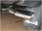 TRD catback drone?
 Oil change 2nd gen
 Drive Shaft Grease
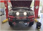 Keeping track of my stuff
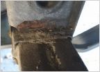 2007 TRD rust bucket!
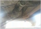 Went to Fluid Film my frame and noticed...
Drive Shaft Vibrations Solved Step-by-Step
Discussion in '2nd Gen. Tacomas (2005-2015)' started by TscotR214, Oct 18, 2012.
Page 1 of 60
Page 1 of 60

