-
Welcome to Tacoma World!
You are currently viewing as a guest! To get full-access, you need to register for a FREE account.
As a registered member, you’ll be able to:- Participate in all Tacoma discussion topics
- Communicate privately with other Tacoma owners from around the world
- Post your own photos in our Members Gallery
- Access all special features of the site
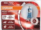 Brightest 9003 H4 bulb for a Tacoma
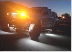 Good rock lights?
 Bed Light Install w/ Interior Switch, Tailgate Trigger Pin and Override.....
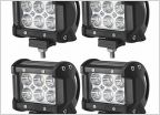 Relay or no relay?
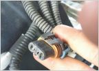 Lightbar wiring to fog lights
New switches, lights = new problems!!!
Discussion in 'Lighting' started by RacerAV, Nov 24, 2012.
Page 1 of 2
Page 1 of 2