-
Welcome to Tacoma World!
You are currently viewing as a guest! To get full-access, you need to register for a FREE account.
As a registered member, you’ll be able to:- Participate in all Tacoma discussion topics
- Communicate privately with other Tacoma owners from around the world
- Post your own photos in our Members Gallery
- Access all special features of the site
 Sumo Springs
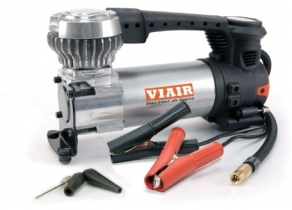
 Experience with Air Armor M240 Air Compressor?
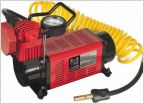 Beach Vacation Gear Help
 20 LED strip
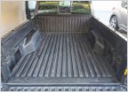 My Experience with Raptor Lining My Bed
P219B Diagnosing
Discussion in '2nd Gen. Tacomas (2005-2015)' started by Jalenrobb1, Dec 25, 2024.