-
Welcome to Tacoma World!
You are currently viewing as a guest! To get full-access, you need to register for a FREE account.
As a registered member, you’ll be able to:- Participate in all Tacoma discussion topics
- Communicate privately with other Tacoma owners from around the world
- Post your own photos in our Members Gallery
- Access all special features of the site
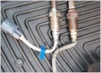 2006-2007 O2 (Air/Fuel) Oxygen Upstream Sensor
 OEM Toyota updated Oil Filter Chart
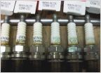 2008 V6 Spark Plugs 6 Speed Manual Denso/NGK
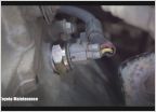 Is this switch supposed to have a gasket?
 2015 Horn Issue
power steering pump
Discussion in '2nd Gen. Tacomas (2005-2015)' started by thewarriordinghy, Oct 3, 2015.