

-
Welcome to Tacoma World!
You are currently viewing as a guest! To get full-access, you need to register for a FREE account.
As a registered member, you’ll be able to:- Participate in all Tacoma discussion topics
- Communicate privately with other Tacoma owners from around the world
- Post your own photos in our Members Gallery
- Access all special features of the site
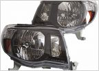 Thoughts on Kensun HIDs
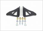 No drill roof mount???
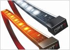 Running board LED wiring help
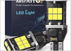 What LED reverse lights are you using?
 Wiring Help
3RD Brake Light Mod
Discussion in 'Lighting' started by sy272004, Oct 12, 2015.


