

-
Welcome to Tacoma World!
You are currently viewing as a guest! To get full-access, you need to register for a FREE account.
As a registered member, you’ll be able to:- Participate in all Tacoma discussion topics
- Communicate privately with other Tacoma owners from around the world
- Post your own photos in our Members Gallery
- Access all special features of the site
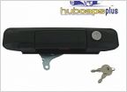 Tailgate lock
 Proper fluids for Aging 2.7L
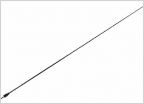 Best Short antenna on the market
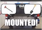 Tacoma Mod: Quick Fist bed rail mounts for tools (axe/shovels)
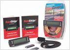 ScanGauge- Which one do you guys use?
(Feeler) LED Turn Signal Solution for Tacomas with DRLs - WORK IN PROGRESS
Discussion in '2nd Gen. Tacomas (2005-2015)' started by will.carroll7, Jan 11, 2017.


