1. Welcome to Tacoma World!

    You are currently viewing as a guest! To get full-access, you need to register for a FREE account.

    As a registered member, you’ll be able to:
    • Participate in all Tacoma discussion topics
    • Communicate privately with other Tacoma owners from around the world
    • Post your own photos in our Members Gallery
    • Access all special features of the site

Help Wiring Pod Lights and Light Bar

Discussion in 'Lighting' started by Gnarman, Feb 8, 2017.

  1. Feb 8, 2017 at 3:47 PM
    #1
    Gnarman

    Gnarman [OP] Well-Known Member

    Joined:
    Jan 24, 2016
    Member:
    #175919
    Messages:
    746
    Gender:
    Male
    Southwest
    Vehicle:
    2016 dbcb trd off road quicksand lb
    ARB Shell, BP51, 255/85/16 ST MAXX, SCS Ray 10 Matte Bronze, Caliraised led 32 inch/side shooter/amber pods, floor mats, start x remote start, auxbeam 8 gang switch panel, diode dynamics hid lows, Australian Shepherd
    Hey guys, I was wondering if anyone could give me a solid answer on what I need. I am wiring up the 32 inch Caliraised Stealth set up on my 3rd gen as well as the 20 watt OSRAM pods.

    I will be splicing in the tacoma style switches that are sold on the Caliraised website into the stock Caliraised harness included (dual leg for the pods and single for the bar). I wanted to know what fuse I need to tap inside the cab and how to do it to run the two switches. I will also be using the 3d printed switch mount from Shapeways. Links below to the switches and wiring harness. Any help especially pictures is greatly appreciated. Thank you!

    https://caliraisedled.com/collections/accessories (switches)
     
  2. Feb 8, 2017 at 4:22 PM
    #2
    MeefZah

    MeefZah -----------

    Joined:
    Jul 11, 2014
    Member:
    #133704
    Messages:
    3,814
    Gender:
    Male
    First Name:
    Mark
    Lexington, Ohio
    Vehicle:
    '24 4R ORP
    As to the fuse to tap, do you want the lights to be able to be turned on all the time, or only with the ignition on?

    The switch to the relay draws milliamps, so any fuse will do. If you want the lights to turn on all the time, regardless of key position, you could use the 5a 'AW1' fuse, it is always hot. For accessories that I want to turn off with the ignition, I use the 15a "accessory (power) socket" fuse. Some degree of trial and error with various fuses can get you similar results, but these two I have personally used / checked.

    My suggestion for fuse tapping is to use the Littelfuse Mini-ATO tap:

    http://www.littelfuse.com/~/media/c...ders/littelfuse-add-a-circuit-fhm02-fha02.pdf

    and then just piggyback the power connection from one switch to the next. The mini-ATO isn't exactly our style of fuse, but it works fine.
     
  3. Feb 8, 2017 at 4:25 PM
    #3
    Gnarman

    Gnarman [OP] Well-Known Member

    Joined:
    Jan 24, 2016
    Member:
    #175919
    Messages:
    746
    Gender:
    Male
    Southwest
    Vehicle:
    2016 dbcb trd off road quicksand lb
    ARB Shell, BP51, 255/85/16 ST MAXX, SCS Ray 10 Matte Bronze, Caliraised led 32 inch/side shooter/amber pods, floor mats, start x remote start, auxbeam 8 gang switch panel, diode dynamics hid lows, Australian Shepherd
    @MeefZah Thank you man! I just want them to work when the truck is turned on. Thank you for all of your help!
     
  4. Feb 8, 2017 at 4:30 PM
    #4
    MeefZah

    MeefZah -----------

    Joined:
    Jul 11, 2014
    Member:
    #133704
    Messages:
    3,814
    Gender:
    Male
    First Name:
    Mark
    Lexington, Ohio
    Vehicle:
    '24 4R ORP
    No prob. So yeah, I would use the 15a "accessory socket" fuse, that's a good choice because in the unlikely event you blow it, you aren't going to be SOL. You will have to discard the plastic cover that goes over the fuse box to use the fuse taps, so either take a photo of the label or peel the label off and stick it in the owner's manual so you still have the fuse schematic available to you out on the road.

    Incidentally, a decent ground to use (for the illumination of the switch) is the bolt that holds the fusebox up to the dash, it's a 10mm nut easily accessible from the underside of the dash and is right by the fusebox, so you can run the wires neatly together. It may appear to be plastic insulated from ground, but it is not - the bolt goes through the metal sub-structure of the dash and is a ground.
     
  5. Feb 8, 2017 at 4:39 PM
    #5
    MeefZah

    MeefZah -----------

    Joined:
    Jul 11, 2014
    Member:
    #133704
    Messages:
    3,814
    Gender:
    Male
    First Name:
    Mark
    Lexington, Ohio
    Vehicle:
    '24 4R ORP
    This is the best picture I can muster up, shows the fuse tap (going to the 5a constant power AW1 fuse) and the ground.

    [​IMG]
     
  6. Feb 8, 2017 at 8:35 PM
    #6
    Gnarman

    Gnarman [OP] Well-Known Member

    Joined:
    Jan 24, 2016
    Member:
    #175919
    Messages:
    746
    Gender:
    Male
    Southwest
    Vehicle:
    2016 dbcb trd off road quicksand lb
    ARB Shell, BP51, 255/85/16 ST MAXX, SCS Ray 10 Matte Bronze, Caliraised led 32 inch/side shooter/amber pods, floor mats, start x remote start, auxbeam 8 gang switch panel, diode dynamics hid lows, Australian Shepherd

    Awesome, thank you so much man, I really appreciate all of the help.
     
  7. Feb 8, 2017 at 8:55 PM
    #7
    Gnarman

    Gnarman [OP] Well-Known Member

    Joined:
    Jan 24, 2016
    Member:
    #175919
    Messages:
    746
    Gender:
    Male
    Southwest
    Vehicle:
    2016 dbcb trd off road quicksand lb
    ARB Shell, BP51, 255/85/16 ST MAXX, SCS Ray 10 Matte Bronze, Caliraised led 32 inch/side shooter/amber pods, floor mats, start x remote start, auxbeam 8 gang switch panel, diode dynamics hid lows, Australian Shepherd
    Quick question can I piggy back more than one on the same add a fuse or use different ones?
     
  8. Feb 8, 2017 at 9:13 PM
    #8
    MeefZah

    MeefZah -----------

    Joined:
    Jul 11, 2014
    Member:
    #133704
    Messages:
    3,814
    Gender:
    Male
    First Name:
    Mark
    Lexington, Ohio
    Vehicle:
    '24 4R ORP
    For the switches? Yeah, what I would do is run the wire from the add-a-circuit to the #1 switch's input. Piggyback that wire from #1 to the #2 switch's input. This way both switches work independently of each other.

    Alternatively you can just add two wires to the add-a-circuit and run each wire to the respective input on each switch, but this isn't (IMO) as clean as doing it the other way.

    The add a circuit can easily provide 15a and each switch is probably drawing 500ma, so in theory you could run 30+ switches off one add-a-circuit; so there's no issue with that.
     
  9. Feb 8, 2017 at 9:37 PM
    #9
    Gnarman

    Gnarman [OP] Well-Known Member

    Joined:
    Jan 24, 2016
    Member:
    #175919
    Messages:
    746
    Gender:
    Male
    Southwest
    Vehicle:
    2016 dbcb trd off road quicksand lb
    ARB Shell, BP51, 255/85/16 ST MAXX, SCS Ray 10 Matte Bronze, Caliraised led 32 inch/side shooter/amber pods, floor mats, start x remote start, auxbeam 8 gang switch panel, diode dynamics hid lows, Australian Shepherd
    Gotcha, so I would just double solder that connection where it is coming out of the add a fuse and add the connection providing power to the second switch and have two wires coming out of it and then the rest of the wires for the respective switches would just be soldered to the correct ones on the harness? Sorry man I am a newb at this stuff.
     
  10. Feb 8, 2017 at 10:26 PM
    #10
    MeefZah

    MeefZah -----------

    Joined:
    Jul 11, 2014
    Member:
    #133704
    Messages:
    3,814
    Gender:
    Male
    First Name:
    Mark
    Lexington, Ohio
    Vehicle:
    '24 4R ORP
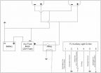
    Well. ...sort of. I know the OEM style switches have more terminals than 3, and I've never torn one apart, so I can't say for sure. I think you are a little off on your explanation. If you have 2 wires coming off the add a circuit then just run one to each switch input power.

    This is how i would wire it, using one wire coming off the aac. This schematic would be for a typical 3 terminal rocker switch. Maybe you can see what I mean, and apply it to your switch:

    20170208_222006.jpg
     
  11. Feb 9, 2017 at 4:07 PM
    #11
    Gnarman

    Gnarman [OP] Well-Known Member

    Joined:
    Jan 24, 2016
    Member:
    #175919
    Messages:
    746
    Gender:
    Male
    Southwest
    Vehicle:
    2016 dbcb trd off road quicksand lb
    ARB Shell, BP51, 255/85/16 ST MAXX, SCS Ray 10 Matte Bronze, Caliraised led 32 inch/side shooter/amber pods, floor mats, start x remote start, auxbeam 8 gang switch panel, diode dynamics hid lows, Australian Shepherd
    Hey buddy quick question so I went to the auto shop here and they had a mini adda fuse but the one they had was up to ten amps and the guy there said that I need to calculate the draw of my pods and bar and then figure out what that number is to discover if that adda fuse will work. Sorry I am very new to wiring still
     
  12. Feb 9, 2017 at 9:42 PM
    #12
    MeefZah

    MeefZah -----------

    Joined:
    Jul 11, 2014
    Member:
    #133704
    Messages:
    3,814
    Gender:
    Male
    First Name:
    Mark
    Lexington, Ohio
    Vehicle:
    '24 4R ORP
    The add a fuse should be good to 15a, I think. Maybe it's 10a, I guess I could be wrong. Whatever the product info says, go with that.

    Either way, the amperage of the fuse you tap into is immaterial - it could be 5a or 25a. Just keep the same amperage rating - remove the fuse from the fusebox, and install the same amperage rating fuse in the add-a-circuit to control that OEM circuit.

    The fuse you install to run the switch is the important one, but the switch is drawing only a few milliamps - as noted above, maybe 500ma. I would put the lowest amperage fuse in there -probably 3a - and it will function fine.

    You are confused about amp draw of the LEDs versus amp draw of the switch, and about what the add-a-circuit powers, and how the LEDs get power. Here's the fast breakdown: The LED pods and bar will draw probably 10-15a, maybe a hair more. But they are powered through the relay that is part of the Caliraised harness. A relay, if you don't understand, is basically an electrically powered switch that is designed to handle higher amperage loads while being activated by a very low amperage trigger. Your switch and fusebox power is the low amperage trigger. The relay and wiring harness is installed directly to the battery and there is a 25 or 30a fuse in line with that power wire in the harness. The relay, if you actually look at it, has 4 prongs - 1 goes to ground, 1 goes to the switch trigger, 1 goes to the battery +, and one goes to the LEDs. So what happens is - the switch is powered from the fusebox. You throw the switch, it energizes maybe 500ma and triggers the relay, which closes and makes the connection between the battery + and the LED power.

    So, the fuse you are asking about and the add-a-circuit are not directly powering the LEDs, they are providing low amperage "trigger" to the relay to control it, which in turn controls the LEDs.
     
    RBfastback likes this.
  13. Feb 10, 2017 at 3:14 PM
    #13
    Gnarman

    Gnarman [OP] Well-Known Member

    Joined:
    Jan 24, 2016
    Member:
    #175919
    Messages:
    746
    Gender:
    Male
    Southwest
    Vehicle:
    2016 dbcb trd off road quicksand lb
    ARB Shell, BP51, 255/85/16 ST MAXX, SCS Ray 10 Matte Bronze, Caliraised led 32 inch/side shooter/amber pods, floor mats, start x remote start, auxbeam 8 gang switch panel, diode dynamics hid lows, Australian Shepherd
    Thank you so much for the explanation, you are the man.
     

Products Discussed in

To Top