

-
Welcome to Tacoma World!
You are currently viewing as a guest! To get full-access, you need to register for a FREE account.
As a registered member, you’ll be able to:- Participate in all Tacoma discussion topics
- Communicate privately with other Tacoma owners from around the world
- Post your own photos in our Members Gallery
- Access all special features of the site
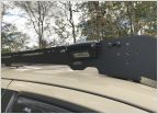 Cleanest way to integrate rock/scene lights and bed lights into roof rack
 HID part needed
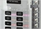 Wiring multiple lights on multiple switches
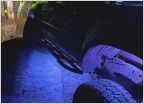 Rock light bonus
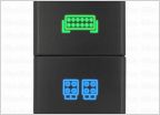 Dual switch install help
OEM to Air On Board Fog Light Switch Wiring
Discussion in 'Lighting' started by Qball 16, Apr 3, 2015.
Page 3 of 3
Page 3 of 3


