-
Welcome to Tacoma World!
You are currently viewing as a guest! To get full-access, you need to register for a FREE account.
As a registered member, you’ll be able to:- Participate in all Tacoma discussion topics
- Communicate privately with other Tacoma owners from around the world
- Post your own photos in our Members Gallery
- Access all special features of the site
 SPod or Switch Pro
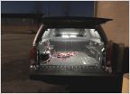 My Shell Interior Lighting Project
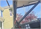
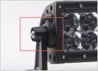 Light bar mounts
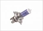 Best headlights for driving
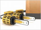 Morimoto 2Stroke 2.0 LED Bulbs: The New Benchmark
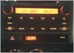 Climate Control Lights
Help changing switches
Discussion in 'Lighting' started by renval, May 12, 2017.