-
Welcome to Tacoma World!
You are currently viewing as a guest! To get full-access, you need to register for a FREE account.
As a registered member, you’ll be able to:- Participate in all Tacoma discussion topics
- Communicate privately with other Tacoma owners from around the world
- Post your own photos in our Members Gallery
- Access all special features of the site
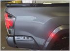 Install Raptor side markers?
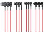 Wolfbox G900- Hardwire Kit Help Needed
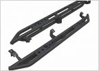 TYGER Star Armor Kit for 2005-2016 Tacoma Double Cab
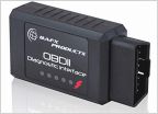 Bluetooth OBD Device
 05+ hi-lift bed mounts?
Installing OEM power window regulators & push button switches
Discussion in '2nd Gen. Tacomas (2005-2015)' started by HomeGrown, Aug 12, 2017.